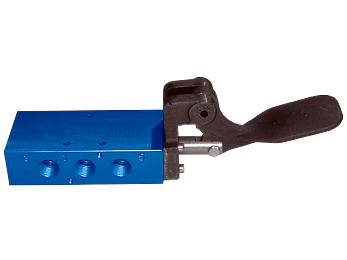




Foot Pedal Manually Actuated Valves - L20, L45 Series
 Product Catalog
- 3/2 & 5/2 spring return and detented options
- In-line mount
- 1/4", 3/8", and 1/2" ports
- Spool construction
- Additional models available, please view downloadable literature
Unable to load products. Please try again.
loading...
loading...
Product Overview
The Automatic Valve Foot Pedal series delivers hands-free pneumatic directional control for industrial applications where operators need both hands free during the work cycle. Built on the proven L20 and L45 compact spool valve platforms, these foot-actuated valves provide 5/2 spring return function in a rugged inline body optimized for demanding machine tool, press, and assembly line environments.
The L20 Foot Pedal valves offer 1/4 and 3/8 NPT port sizes with a flow capacity of 1,770 l/min (Cv 1.8) for 5/2 functions, housed in aluminum bodies with NBR (Buna-N) seals for standard temperature service from -18 to 50 C (0 to 123 F). The spring return design ensures the valve automatically returns to its de-energized state when the operator removes foot pressure, providing an inherently safe control mode for single-acting actuators and other pneumatic circuits.
The foot pedal operator engages a mechanical linkage that shifts the internal spool to direct compressed air from the supply port to the work port while simultaneously exhausting the opposite port. When the operator releases foot pressure, the integral spring drives the spool back to the default position, exhausting the work port and providing positive, repeatable control with every cycle.
Available in model variants for 1/4 port (L2003 body) and 3/8 port (L2004 body), the foot pedal series integrates directly with standard Automatic Valve L20 manifolds, enabling multi-station configurations that combine foot pedal control with solenoid or air pilot operators on a common manifold. The Tapered Tee-Seal construction wipes the spool clean on every stroke, providing superior dirt tolerance and long service life without requiring air line lubrication.
Key Engineering Features
- Hands-Free Directional Control - Foot-actuated spool shifting frees both operator hands for part handling, tooling, or workpiece manipulation during the pneumatic work cycle.
- Tapered Tee-Seal Construction - Bidirectional tapered Tee-Seal flexes to clean the spool on every actuation, mechanically locking in place with no spiral twist or extrusion, wiping away air line sediment to deliver validated 20-million cycle life per SAE test protocols.
- Spring Return Operation - The integral spring automatically returns the valve to its de-energized default position when foot pressure is released, providing fail-safe behavior for single-acting cylinder and single-position actuator applications.
- 5/2 Valve Function - 5-port, 2-position spool function controls double-acting cylinders, directing supply to one actuator port while exhausting the other, with full reversal on spring return.
- Compact Inline Body - Inline mount with 1/4 or 3/8 NPT ports allows direct installation in air lines without manifold adapters, minimizing panel space and plumbing complexity.
- Manifold Compatibility - L20 foot pedal valves mount directly onto A8020 series manifolds alongside solenoid, air pilot, hand lever, palm button, and other L20 operators for flexible multi-station circuit design.
- Aluminum Body with NBR Seals - Lightweight die-cast aluminum valve body with treated Buna-N seals for standard industrial temperature service; fluoroelastomer seal option (suffix A) available for fluid media compatibility requirements.
- Field-Convertible External Pilot - Option B allows field conversion to external pilot supply for applications where inlet pressure at port 1 is below 35 psig (2.4 bar) by rotating the gasket 180 degrees and removing the 1/8 NPTF plug.
Technical Specifications
General Specifications
| Parameter | Specification |
| Valve Series | L20 (1/4 and 3/8 ports), L45 (1/2 port) |
| Valve Function | 5/2 Spring Return |
| Actuation | Manual - Foot Pedal |
| Construction | Spool |
| Mounting | Inline |
| Port Sizes | 1/4", 3/8" NPT (L20); 1/2" NPT (L45) |
| Thread Type | NPT standard; G (BSPP) optional |
| Operating Pressure (2-Position) | 35 to 150 psig (2.4 to 10.3 bar) |
| Flow - L20 (5/2) | 1,770 l/min (Cv 1.8) at 1/4"; 1,770 l/min (Cv 1.8) at 3/8" |
| Flow - L45 (5/2) | 4,800 Nl/min (Cv 4.8) at 1/2" |
| Ambient / Media Temperature | 18 to 50 C (0 to 123 F) |
| Fluid Media | Filtered compressed air or inert gas |
| Filtration Recommendation | 50 microns or better |
| Valve Body Material | Aluminum |
| Spool Material | Aluminum |
| Seal Material | Treated Buna-N (NBR); Fluoroelastomer optional (Option A) |
| Weight (L20 - 5/2) | 0.7 kg (1.1 lb) |
Flow Performance Data
| Series | Port Size | Function | Flow l/min (Cv) | Body Material | Seal | Weight kg (lb) |
| L20 | 1/4" | 5/2 | 1,770 (1.8) | Aluminum | NBR | 0.7 (1.1) |
| L20 | 3/8" | 5/2 | 1,770 (1.8) | Aluminum | NBR | 0.7 (1.1) |
| L45 | 1/2" | 5/2 | 4,800 (4.8) | Aluminum | NBR | 0.68 (1.5) |
Certifications & Compliance
| Certification/Standard | Detail |
| CSA | C22.2 and UL STD 429 certified for solenoid-actuated variants in the L20 and L45 platform. |
| CE | CE marking per EMF and Low Voltage Directives for applicable models. |
| Factory Mutual (FM) | Explosion-proof environments certification available on solenoid operator variants (option Y). |
| ATEX | Explosion-proof environments certification available on solenoid operator variants (option Z). |
| SAE Cycle Testing | Tapered Tee-Seal validated to 20 million cycles with rust and water injection every 864,000 cycles per SAE test protocol. |
Typical Applications & Industries
Machine Tool and Metal Fabrication
- Drill press, milling machine, and lathe clamping circuits where the operator needs both hands on the workpiece or tooling during the clamping and release cycle.
- Hydraulic and pneumatic vise actuation on machining centers, allowing the operator to clamp and unclamp parts with a single foot stroke while positioning the next workpiece with both hands.
- Metal stamping and punch press auxiliary circuits for part ejection or die cushion control where foot activation integrates naturally with the operator's production rhythm.
- Deburring and grinding stations where both hands guide the workpiece against the abrasive tool and a foot pedal controls a hold-down clamp or part positioning fixture.
Assembly and Test Operations
- Manual assembly benches for pneumatic press fitting, riveting, and staking operations where the operator holds the assembly in alignment and actuates a pneumatic press with foot actuation.
- Leak test and functional test fixtures where the operator loads and unloads parts by hand while the foot pedal sequences the test air supply to the part under test.
- Cable and hose assembly crimping stations where both hands guide the fitting into the crimping die and the foot pedal initiates the crimp cycle.
- Ergonomic workstation design in automotive component assembly where foot-controlled air reduces repetitive hand motion and enables faster cycle times.
Woodworking and Furniture Manufacturing
- Edge banding and panel pressing operations where the operator feeds panels with both hands and uses foot control to apply clamping pressure or trigger adhesive injection.
- Pneumatic stapling, nailing, and fastener driving fixtures on furniture assembly lines, eliminating the need to release the workpiece to actuate a hand-operated valve.
- Spray booth and finishing line part holding fixtures activated by foot pedal for hands-free part orientation during coating operations.
- Router table and shaper clamping circuits enabling the operator to maintain two-hand workpiece control throughout the cut.
Packaging and Material Handling
- Manual bagging, sealing, and labeling stations where the operator positions the package with both hands and uses a foot pedal to trigger the sealing or labeling mechanism.
- Pneumatic conveyor divert and gate control in sortation lines where a line attendant directs product flow by foot rather than interrupting material handling to operate a button.
- Vacuum cup and gripper systems on manual pick stations, enabling operators to pick and place parts without releasing grip to activate the vacuum circuit.
- Banding and strapping machines where foot actuation completes the strap cycle while the operator holds the package in position.
Food Processing and Agricultural Equipment
- Meat and poultry processing equipment where gloved operators use foot pedals to control air cylinders for portion cutting, trimming, and clamping without contaminating hand-operated controls.
- Agricultural machinery cab controls and implement actuation where operator hands are occupied with steering and implement positioning.
- Dairy and beverage processing fill and seal stations where sanitation requirements favor foot-actuated controls over frequently touched hand controls.
- Greenhouse and nursery automation for pot and tray handling equipment with foot-actuated gripper release.
Welding and Metal Joining
- Resistance spot welding and projection welding fixtures where the electrode force is applied pneumatically and the operator controls the weld cycle by foot while guiding the workpiece with both hands.
- MIG and TIG welding positioners and rotary fixtures where the welder controls rotation speed or part clamping by foot actuation.
- Pneumatic pipe bending and forming machines where the operator controls bend angles by foot while guiding the workpiece through the die.
- Induction heating and brazing stations where foot control of the air supply prevents operator contact with heated components.
Ordering and Model Number Configuration
Automatic Valve L20 series foot pedal valves use a structured model number system. The example below decodes model L2003AAKR.
|
Model: L2003AAKR
L20 Series (L20 Compact Spool)
03 Port Size (03 = 1/4", 04 = 3/8")
A Body Type (A = 5/2 Single, B = 5/3 Detented, C/D/E = 5/3 Spring Center variants)
A Center Operator (A = single, B = double)
K Operator Code (K = Foot Pedal)
R Return Type (R = Spring Return) |
Standard port threads are NPT. For G (BSPP) threads, add suffix W to the model number.
For fluoroelastomer seals (FKM), add suffix A to the model number.
For external pilot supply (below 35 psig inlet), add suffix B. Field conversion is also possible without reordering.
Option D (Dustproof) plugs vent ports for extremely contaminated environments.
Stainless steel body options: suffix S = 303 SS, suffix SS = 316 SS (L20 only).
Additional models beyond the standard listing are available. Consult Automatic Valve or download product literature for the complete model number matrix.
Accessories
L20 Manifolds
A8020 series manifolds accept L20 foot pedal valves alongside other L20 operators on common inlet and exhaust ports. Available in 2 to 10 station configurations.
| Stations | Model Number | Port Size | Weight kg (lb) |
| 2 | A8020-002 | 3/8 | 0.42 (0.9) |
| 4 | A8020-004 | 3/8 | 0.6 (1.3) |
| 6 | A8020-006 | 3/8 | 0.8 (1.7) |
| 8 | A8020-008 | 3/8 | 1.0 (2.2) |
| 10 | A8020-010 | 3/8 | 1.19 (2.7) |
Interposed Flow Controls
Model B8022-005 mounts between the L20 valve body and the manifold to restrict exhaust air flow from port 2 to port 3 and port 4 to port 5, providing cylinder exhaust speed control without external flow control valves.
| Series | Model Number | Dimension H mm (in) | Weight kg (lb) |
| L20 | B8022-005 | 12.7 (0.50) | 0.09 (0.19) |
Blocking Disk
Model A8020-202 allows individual manifold stations to be blocked when not in use, maintaining system pressure while leaving unused stations inactive.
| Series | Model Number | Application |
| L20 | A8020-202 | Block unused manifold station |
Related Products & Accessories
- L20 Series Cam Roller Mechanically Actuated Valves - Mechanically actuated companion to the foot pedal series for machine-controlled applications using cam or roller actuation. https://www.automaticvalve.com/series/2820-cam-roller
- L20 Series Foot Treadle Manually Actuated Valves - Treadle-actuated variant offering 5/2 and 5/3 functions for applications requiring a larger actuation platform or defined foot position. https://www.automaticvalve.com/series/2823-foot-treadle
- L20 Series Hand Lever Manually Actuated Valves - Hand lever variants covering the same L20 platform for applications where hand rather than foot actuation is preferred. https://www.automaticvalve.com/series/2824-hand-lever
- L20 Series Palm Button Manually Actuated Valves - Palm button variants for two-hand no-tie-down control circuits and ergonomic operator-interface applications. https://www.automaticvalve.com/series/2825-palm-button
- Compact Solenoid L Series Valves - Standard Temperature - Solenoid-actuated L20 and L65 directional control valves for automated circuit integration alongside manual operator stations. https://www.automaticvalve.com/series/2979-compact-solenoid-l-series-valves-standard-temperature-applications
- Energy Isolation Valves - 15 Series Lockout L-O-X Valves - Upstream energy isolation valves required for OSHA lockout/tagout compliance at any machine or workstation using foot pedal or other manual valves. https://www.automaticvalve.com/series/3010-energy-isolation-valves
Frequently Asked Questions (FAQ)
Q: What valve function does the foot pedal valve provide?
A: The Automatic Valve L20 foot pedal series provides a 5/2 (5-port, 2-position) spring return function. When the operator depresses the pedal, the spool shifts to connect port 1 to port 4 and port 2 to port 3. When foot pressure is released, the spring returns the spool to its default position connecting port 1 to port 2 and port 4 to port 5.
Q: What is the maximum operating pressure for the L20 foot pedal valve?
A: Maximum operating pressure is 150 psig (10.3 bar). Minimum operating pressure for 2-position spring return function is 35 psig (2.4 bar).
Q: What port sizes are available for the foot pedal series?
A: L20 foot pedal valves are available in 1/4 inch NPT (model L2003AAKR) and 3/8 inch NPT (model L2004AAKR). L45 series provides 1/2 inch NPT port size.
Q: What is the flow capacity of the L20 foot pedal valve?
A: The L20 foot pedal valve provides 1,770 l/min (Cv 1.8) flow capacity for the 5/2 function. The larger L45 series at 1/2 inch port size provides 4,800 Nl/min (Cv 4.8).
Q: Can the foot pedal valve be used without air line lubrication?
A: Yes. The Tapered Tee-Seal design does not require air line lubrication for normal service. Lubrication is recommended, but not mandatory, to maximize seal and spool service life. If lubrication is used, select petroleum-based oil with ISO 32 or lighter viscosity, aniline point between 82 C and 99 C, and avoid phosphate additives.
Q: What temperature range is the foot pedal valve rated for?
A: Standard L20 and L45 foot pedal valves with Buna-N seals are rated for ambient and media temperatures from -18 C to 50 C (0 F to 123 F). For fluids or environments outside this range, specify the fluoroelastomer seal option (suffix A).
Q: Can L20 foot pedal valves be mounted on a manifold with solenoid valves?
A: Yes. L20 foot pedal valves are fully compatible with the A8020 series L20 manifolds and can be mounted at any station alongside solenoid, air pilot, hand lever, or palm button operators. All share the same body footprint and manifold bolt pattern.
Q: How do I convert the foot pedal valve to external pilot supply?
A: Field conversion requires removing the solenoid and cap, rotating the gasket 180 degrees to cover the internal pilot hole in the valve body, refastening the gasket and cap, and then removing the 1/8 NPTF pipe plug from the cap to connect external pilot air. Torque the M3 cap screws to 1.02 N-m (9 in-lbs). External pilot pressure must be between 35 and 150 psig.
Q: What service kit should I use for the L20 foot pedal valve?
A: Use service kit K-L20-SGL for the standard single-spring-return L20 body. This kit includes 6 Tee-Seals, 1 piston seal, 1 spring, and lubricant. For fluoroelastomer seals, use K-L20-SGL-A.
Q: Is the foot pedal valve suitable for use as a safety valve or emergency stop device?
A: No. The L20 foot pedal valve is a directional control valve for normal machine cycle control. It is not rated or certified as a safety valve, press control, or emergency stop device. Safety-rated circuits require dedicated dual-channel press control valves per OSHA and ANSI B11 requirements. Install an Automatic Valve 15 Series L-O-X lockout valve upstream for energy isolation during maintenance.
Q: Are stainless steel body options available for the foot pedal series?
A: Yes. The L20 platform supports 303 stainless steel body (Option S) and 316 stainless steel body (Option SS) for corrosive environment applications. All external parts are corrosion resistant in these configurations.
Q: What filtration is required upstream of the foot pedal valve?
A: Automatic Valve recommends filtration to 50 microns or better upstream of any L20 or L45 valve. Use a filter-regulator unit with a coalescing element to remove particulate and water vapor. For environments below 4 C (40 F), air must be dried to a dew point below the minimum operating temperature to prevent ice formation inside the valve.
Q: How does the foot pedal relate to OSHA lockout/tagout compliance?
A: The foot pedal valve controls machine actuation during normal operation. OSHA 29 CFR 1910.147 requires that energy be isolated and locked out before maintenance personnel access the machine. Install an Automatic Valve 15 Series L-O-X lockout valve upstream of the foot pedal valve so that maintenance personnel can block the air supply and padlock it in the closed, exhausted position before servicing.
Installation & Maintenance Guidelines
- Mount the valve inline in any orientation. Vertical mounting with the foot pedal facing downward is preferred for condensate drainage and natural operator ergonomics.
- Supply filtered air at 50 microns or better. Use a coalescing filter-regulator-lubricator (FRL) upstream of the valve station to remove moisture, particulate, and pipe scale.
- Maintain supply pressure between 35 and 150 psig (2.4 to 10.3 bar) for 2-position spring return function. Do not exceed 150 psig maximum pressure.
- For applications where inlet pressure at port 1 is below 35 psig (2.4 bar), convert to external pilot supply using Option B or perform the field conversion by rotating the gasket 180 degrees and connecting pilot air to the 1/8 NPTF external pilot port.
- Do not restrict the exhaust port. Restricted exhaust causes back pressure that reduces effective shifting force and can cause erratic valve operation. Install an exhaust silencer with a flow capacity equal to or greater than the valve exhaust capacity.
- Air line lubrication is not required but is recommended to maximize service life. Use petroleum-based oils with an ISO 32 or lighter viscosity and an aniline point between 82 C (180 F) and 99 C (210 F). Do not use phosphate-type additives.
- For media temperatures below 4 C (40 F), supply air must be dried to a dew point below the minimum operating temperature to prevent ice formation inside the valve.
- Mount the foot pedal guard to prevent accidental actuation in high-traffic areas or where falling objects could inadvertently depress the pedal.
- Torque operator cap M3 screws to 1.02 N-m (9 in-lbs) plus or minus 10 percent when reassembling after service.
- Verify valve function after installation by cycling the foot pedal several times at minimum operating pressure before placing the machine in production service.
Warranty & Global Support
Automatic Valve provides a one-year warranty on all products, covering defects in material and workmanship from the date of purchase.
Technical support is available from Automatic Valve at (248) 474-6761.
For product selection, configuration assistance, and distributor information, visit automaticvalve.com or contact Automatic Valve directly.
For complete technical data, dimensional drawings, and product catalog downloads, visit the Automatic Valve website at automaticvalve.com or request the Compact Spool Valves product catalog.
Download Catalog: https://www.automaticvalve.com/documents/415/AV_Compact_L-Series_Manual-Mechanical_Valves_AV-C-MMV_en.pdf
Download Documents
Foot Pedal