



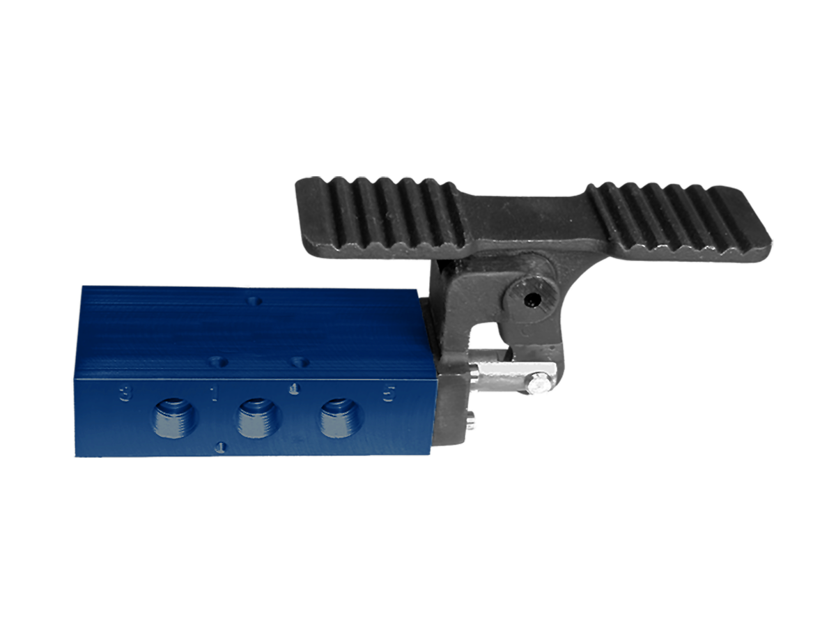
Foot Treadle Manually Actuated - L20 Series
 Product Catalog
- 5/2 & 5/3 spring return and detented options
- In-line mount
- 1/4" & 3/8" ports
- Spool construction
- Additional models available, please view downloadable literature
loading...
loading...
Product Overview
The Automatic Valve Foot Treadle series provides full-foot, manually actuated pneumatic directional control for industrial workstations where operator ergonomics, larger actuation area, or defined foot positioning is required. Built on the proven L20 compact spool valve platform, these treadle-actuated valves offer both 5/2 spring return and 5/3 detented center position functions in a rugged inline body for press, assembly, machine tool, and hands-free operation applications.
Unlike the pedal variants that use a smaller actuating surface, the foot treadle employs a broad platform that accommodates the full sole of an operator's work boot, providing comfortable and positive actuation even when wearing heavy personal protective footwear. The treadle geometry provides a mechanical advantage that reduces required actuation force while delivering consistent spool travel on every stroke.
The L20 Foot Treadle series covers 8 series variants including 5/2 spring return (detented and non-detented) and 5/3 center-position configurations with Block, Exhaust, and Pressure center options. Port sizes are 1/4 inch (L2003 body) and 3/8 inch (L2004 body), with a flow capacity of 1,770 l/min (Cv 1.8) for 5/2 function and 1,381 l/min (Cv 1.4) for 5/3 function.
The 5/3 configurations are particularly valuable for applications requiring cylinder mid-travel stopping, pressure equalization, or a defined safe rest position when the operator releases the treadle. The Block center stops the cylinder at any position in its stroke. The Exhaust center exhausts both work ports, retracting single-acting loads under their own weight. The Pressure center connects both work ports to supply for pressure-balanced holding without cylinder drift.
Key Engineering Features
- Full-Sole Treadle Platform - The broad treadle footprint accommodates work boots and safety footwear, providing comfortable, positive, and fatigue-reducing actuation compared to smaller pedal designs.
- 5/2 and 5/3 Function Options - Available in 5/2 spring return for standard single-acting cylinder control and 5/3 spring center configurations (Block, Exhaust, Pressure center) for applications requiring a defined intermediate position when the operator releases the treadle.
- Spring Return and Detented Variants - Spring return treadles automatically restore to the default valve position when the operator lifts their foot. Detented treadle versions hold the shifted position until the treadle is deliberately depressed a second time, supporting latched circuit logic.
- Tapered Tee-Seal Construction - Bidirectional tapered Tee-Seal wipes the spool bore on every stroke, mechanically locks without spiral twist or extrusion, and maintains 20-million-cycle validated service life per SAE test protocols with rust and water injection.
- Inline Compact Body - Inline mount with 1/4 or 3/8 NPT ports allows direct installation in air lines. The same L20 body footprint as other operator types enables manifold mounting and multi-station configurations.
- Manifold Compatibility - L20 foot treadle valves mount on A8020 series manifolds at any station, mixing with solenoid, cam roller, hand lever, palm button, and other L20 operators on a common manifold body.
- Aluminum Body with NBR Seals - Die-cast aluminum body with treated Buna-N seals for standard temperature service from -18 to 50 C. Fluoroelastomer seals available as Option A.
- Low Actuation Force - Treadle geometry multiplies foot force for reduced operator effort at any inlet pressure within the specified operating range.
Technical Specifications
General Specifications
| Parameter | Specification |
| Valve Series | L20 |
| Valve Functions | 5/2 Spring Return; 5/3 Block Center; 5/3 Exhaust Center; 5/3 Pressure Center |
| Operator Types | Spring Return (R) and Detented (M) treadle variants |
| Actuation | Manual - Foot Treadle |
| Construction | Spool |
| Mounting | Inline |
| Port Sizes | 1/4" and 3/8" NPT |
| Thread Type | NPT standard; G (BSPP) optional |
| Operating Pressure (5/2) | 35 to 150 psig (2.4 to 10.3 bar) |
| Operating Pressure (5/3) | 50 to 150 psig (3.5 to 10.3 bar) |
| Flow (5/2) | 1,770 l/min (Cv 1.8) |
| Flow (5/3) | 1,381 l/min (Cv 1.4) |
| Ambient / Media Temperature | 18 to 50 C (0 to 123 F) |
| Fluid Media | Filtered compressed air or inert gas |
| Filtration Recommendation | 50 microns or better |
| Valve Body Material | Aluminum |
| Spool Material | Aluminum |
| Seal Material | Treated Buna-N (NBR); Fluoroelastomer optional (Option A) |
| Weight (5/2 and 5/3) | 0.7 kg (1.5 lb) |
Flow Performance Data
| Series | Port Size | Function | Flow l/min (Cv) | Body Material | Seal | Weight kg (lb) |
| L20 | 1/4" | 5/2 | 1,770 (1.8) | Aluminum | NBR | 0.7 (1.5) |
| L20 | 3/8" | 5/2 | 1,770 (1.8) | Aluminum | NBR | 0.7 (1.5) |
| L20 | 1/4" | 5/3 | 1,381 (1.4) | Aluminum | NBR | 0.7 (1.5) |
| L20 | 3/8" | 5/3 | 1,381 (1.4) | Aluminum | NBR | 0.7 (1.5) |
Certifications & Compliance
| Certification/Standard | Detail |
| CSA | C22.2 and UL STD 429 for L20 platform solenoid variants. Manual foot treadle models require no electrical certification. |
| CE | CE marking applicable per EMF and Low Voltage Directives for solenoid platform variants. |
| SAE Cycle Testing | Tapered Tee-Seal validated to 20 million cycles with rust and water injection every 864,000 cycles per SAE test protocol. |
Typical Applications & Industries
Press and Stamping Operations
- Hydraulic press and pneumatic press auxiliary circuits where the operator controls part clamping, part ejection, or workpiece positioning using both hands while initiating the press cycle with the foot treadle.
- Brake press backgauge positioning circuits where the foot treadle controls air clamps or air brakes while the operator positions sheet metal against the gauge.
- Pneumatic punch and form press die cushion circuits where the treadle controls cushion pressure before the ram descends.
- Riveting and staking operations at manual assembly benches where the treadle initiates the pneumatic press force while the operator holds the assembly in alignment.
Welding and Metal Joining
- Resistance spot welding electrode approach and hold circuits where the treadle controls electrode force while the welder positions the assembly.
- Pneumatic welding positioner rotation and clamping where the operator uses both hands to feed filler material and the treadle controls rotation speed or part clamping.
- Pipe and tube bending fixtures where the treadle controls bending cylinder advance and the operator guides the workpiece through the die.
- Pneumatic brazing and induction heating fixtures where the treadle controls part clamping and the operator positions torch or induction head with both hands.
Machine Tool and Metalworking
- Lathe and mill workholding fixture clamping using foot treadle control while the operator positions the workpiece with both hands for precise part location.
- Surface grinder and cylindrical grinder wheel dresser and workpiece clamping circuits controlled by treadle for vibration-free setup.
- Drill press vise and indexing table circuits where foot treadle allows single-operator loading and unloading without interrupting the drilling sequence.
- Deburring station part holding and fixture clamping for two-handed deburring tool operation.
Assembly and Test Benches
- Pneumatic torque multiplier and fastener drive fixtures where the treadle activates the torque tool while the operator holds the assembly and positions the fastener.
- Press fit and force insertion benches where the treadle engages the press cylinder while the operator aligns the component for precise mating.
- Functional test and leak test fixtures at end-of-line quality stations where the operator loads the part with both hands and triggers the test air supply with the treadle.
- Cable and wiring harness assembly fixtures where the treadle controls tension or clamping while the operator routes conductors.
Woodworking and Composites
- Pneumatic edge clamp and vacuum press circuits at cabinet and furniture assembly stations where the treadle controls clamping pressure and the operator positions panels.
- Router table, shaper, and tenoning machine workpiece hold-down circuits for two-handed workpiece control throughout the cut.
- Adhesive application and bonding fixture clamping where the treadle applies clamp force after the operator positions the glued assembly.
- Composite layup and molding fixture clamping for two-handed ply positioning.
Food Processing and Packaging
- Manual portioning and filling stations where gloved food handlers use treadle control to dispense or clamp without touching hand-operated controls.
- Seal and crimp stations at packaging lines where the treadle initiates the sealing cycle while the operator guides the package.
- Agricultural equipment operator controls where both hands manage implements and treadle controls auxiliary pneumatic circuits.
- Meat and poultry trimming fixtures where safety regulations require hands-only contact with product and foot control of clamping and ejection.
Ordering and Model Number Configuration
Automatic Valve L20 foot treadle valves use the standard L20 model number system. The example below decodes model L2003BALM.
|
Model: L2003BALM
L20 Series (L20 Compact Spool)
03 Port Size (03 = 1/4", 04 = 3/8")
B Body Type / Function (A = 5/2, B = 5/2 Detented, C = 5/3 Block, D = 5/3 Exhaust, E = 5/3 Pressure)
A Center Operator
L Operator Code (L = Foot Treadle)
M Return Type (M = Detented / Maintained; R = Spring Return; N = Spring Center) |
Standard port threads are NPT. For G (BSPP) threads, add suffix W to the model number.
For fluoroelastomer seals (FKM), add suffix A to the model number.
Option B provides external pilot supply for inlet pressures below 35 psig. Field conversion is also possible.
Option D (Dustproof) plugs vent ports for very contaminated environments.
Stainless steel body options: suffix S = 303 SS, suffix SS = 316 SS (L20 only).
Additional models including 5/3 Pressure center variants are available. Consult Automatic Valve or the product catalog for the complete model number matrix.
Minimum operating pressure for 5/3 functions is 50 psig (3.5 bar).
Accessories
L20 Manifolds
A8020 series manifolds accept L20 foot treadle valves alongside other L20 operator types on common inlet and exhaust ports.
| Stations | Model Number | Port Size | Weight kg (lb) |
| 2 | A8020-002 | 3/8 | 0.42 (0.9) |
| 4 | A8020-004 | 3/8 | 0.6 (1.3) |
| 6 | A8020-006 | 3/8 | 0.8 (1.7) |
| 8 | A8020-008 | 3/8 | 1.0 (2.2) |
| 10 | A8020-010 | 3/8 | 1.19 (2.7) |
Interposed Flow Controls
Model B8022-005 provides exhaust speed control between the valve body and manifold for cylinder speed adjustment.
| Series | Model Number | Dimension H mm (in) | Weight kg (lb) |
| L20 | B8022-005 | 12.7 (0.50) | 0.09 (0.19) |
Related Products & Accessories
- L20 Series Foot Pedal Manually Actuated Valves - Compact foot pedal variant on the L20 platform for applications requiring a smaller actuation footprint. https://www.automaticvalve.com/series/2821-foot-pedal
- L20 Series Cam Roller Mechanically Actuated Valves - Machine-actuated companion series for automatic position sensing and sequence control. https://www.automaticvalve.com/series/2820-cam-roller
- L20 Series Hand Lever Manually Actuated Valves - Hand lever variants for manually switched directional control on the same L20 platform. https://www.automaticvalve.com/series/2824-hand-lever
- Compact Solenoid L Series Valves - Standard Temperature - Solenoid-actuated L20 valves for automated circuit integration alongside foot treadle control stations. https://www.automaticvalve.com/series/2979-compact-solenoid-l-series-valves-standard-temperature-applications
- Energy Isolation Valves - 15 Series Lockout L-O-X Valves - Upstream energy isolation for OSHA lockout/tagout compliance at any workstation using foot treadle or other manual valves. https://www.automaticvalve.com/series/3010-energy-isolation-valves
Frequently Asked Questions (FAQ)
Q: What is the difference between the foot treadle and the foot pedal valve?
A: The foot treadle provides a larger, full-sole actuation platform that accommodates work boots and heavy PPE footwear, making it more ergonomic for sustained use or when precise foot positioning on a small pedal is difficult. The foot pedal uses a smaller actuation surface suited to lighter-duty or space-constrained installations. Both use the same L20 valve body and Tapered Tee-Seal spool construction.
Q: What center position options are available for the 5/3 foot treadle valves?
A: Three 5/3 center position options are available: Block center (all ports blocked when the treadle is released, stopping the cylinder at its current position), Exhaust center (both work ports connected to exhaust, allowing the load to retract under gravity or spring force), and Pressure center (both work ports connected to supply pressure, holding the actuator in a pressure-equalized state).
Q: What is the minimum operating pressure for 5/3 valves?
A: Minimum operating pressure for 5/3 spring center functions is 50 psig (3.5 bar). The 5/2 spring return treadle valve operates from 35 psig (2.4 bar) minimum.
Q: What flow capacity does the L20 foot treadle valve provide?
A: The L20 foot treadle valve provides 1,770 l/min (Cv 1.8) for 5/2 functions and 1,381 l/min (Cv 1.4) for 5/3 functions.
Q: Can the treadle valve hold an actuator in mid-stroke position?
A: Yes, using the 5/3 Block center variant. When the operator releases the treadle with the spool in the center position, all ports are blocked, holding the downstream actuator at its current position. This is valuable for applications where the actuator must dwell at an intermediate position. Note that Block center valves are not suitable for applications where external loads back-drive the cylinder, as blocked ports will trap compressed air and may not prevent actuator movement under high external loads.
Q: Is the L20 foot treadle valve compatible with the L20 manifold system?
A: Yes. The L20 foot treadle valve uses the same body footprint as all other L20 operator types and mounts directly on A8020 series manifolds. Foot treadle stations can be combined with solenoid, cam roller, hand lever, and palm button stations on the same manifold.
Q: What temperature range is the L20 foot treadle valve rated for?
A: Standard NBR seal variants are rated from -18 C to 50 C (0 F to 123 F) for both ambient and media temperature. Specify Option A (fluoroelastomer seals) for applications where the fluid or ambient conditions are not compatible with nitrile seals.
Q: Can I use a detented treadle valve in a latch-type circuit?
A: Yes. The detented (maintained position) treadle variant holds the shifted spool position after the operator lifts their foot, functioning as a latched state in the pneumatic circuit. The treadle must be deliberately depressed again to return the spool to the opposite position. This is useful for applications where a maintained shifted state is needed between operator interventions.
Q: What service kit is used for the L20 foot treadle valve?
A: For 5/2 spring return treadle valves, use K-L20-SGL (or K-L20-SGL-A for fluoroelastomer seals). For 5/3 and double-operator treadle configurations, use K-L20-DBL (or K-L20-DBL-A for fluoroelastomer). Each kit includes 6 Tee-Seals, the appropriate piston seal quantity, a spring (for single models), and lubricant.
Q: Does the treadle valve require guarding against accidental actuation?
A: A protective guard over the treadle is strongly recommended wherever: (1) the treadle is in a high-traffic area where non-operators could accidentally step on it, (2) the controlled function could cause injury if unintentionally actuated, or (3) falling objects could depress the treadle. Guarding requirements are machine-specific and should be evaluated against OSHA 29 CFR 1910 and applicable ANSI machine safety standards.
Q: Can the foot treadle valve be field-converted to external pilot supply?
A: Yes. The field conversion requires removing the operator cap, rotating the gasket 180 degrees to cover the internal pilot hole, refastening the cap, and connecting pilot air at the 1/8 NPTF external pilot port. External pilot pressure must be between 35 and 150 psig.
Q: What is the maximum number of treadle valve stations on one manifold?
A: The A8020 manifold series supports up to 10 stations (model A8020-010). All 10 stations can be foot treadle valves, or any combination of L20 operator types. Blocking disks can be installed at unused stations.
Installation & Maintenance Guidelines
- Mount the treadle valve in an orientation that places the treadle platform at a comfortable height for the operator's foot when seated or standing at the workstation.
- Ensure the treadle platform has adequate clearance for the operator's work boots and PPE footwear. Verify that the treadle stroke is not obstructed by floor debris, cable trays, or adjacent equipment.
- Supply filtered air at 50 microns or better at 35 to 150 psig (2.4 to 10.3 bar) for 5/2 functions. For 5/3 spring center functions, minimum operating pressure is 50 psig (3.5 bar).
- Do not restrict the exhaust port. Use an exhaust silencer with a flow capacity at least equal to the valve exhaust capacity.
- For inlet pressure below 35 psig (2.4 bar), use Option B external pilot supply or perform field conversion by rotating the gasket 180 degrees and connecting pilot air to the 1/8 NPTF external pilot port.
- Lubrication is not required but is recommended. Use petroleum-based oil, ISO 32 or lighter, aniline point 82 to 99 C. Do not use phosphate additives.
- For 5/3 Block center applications, verify that the downstream actuator is designed to hold position under blocked port conditions. Do not use Block center valves on circuits where back-driving loads could force the actuator into an unintended position.
- For media temperatures below 4 C (40 F), supply air must be dried to a dew point below the minimum operating temperature.
- Torque operator cap M3 screws to 1.02 N-m (9 in-lbs) plus or minus 10 percent during reassembly after service.
- Perform a functional check at installation by cycling the treadle through full stroke several times at minimum operating pressure before placing the machine in production service.
Warranty & Global Support
Automatic Valve provides a one-year warranty on all products, covering defects in material and workmanship from the date of purchase.
Technical support is available from Automatic Valve at (248) 474-6761.
For product selection, application engineering, and distributor information, visit automaticvalve.com or contact Automatic Valve directly.
For complete technical data, dimensional drawings, and product catalog downloads, visit automaticvalve.com or request the Compact Spool Valves product catalog.
Download Catalog: https://www.automaticvalve.com/documents/415/AV_Compact_L-Series_Manual-Mechanical_Valves_AV-C-MMV_en.pdf
Download Documents
Foot Treadle