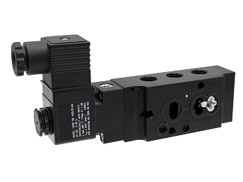




NAMUR Valves - Intrinsically Safe, Standard Temperature Applications -20 to 123 F (-29 to 50 C)
 Operating Instructions
Valve Conversion Instructions
Product Catalog - NAMUR Interface Valves for Hazardous Locations
Operating Instructions
Valve Conversion Instructions
Product Catalog - NAMUR Interface Valves for Hazardous Locations
- Compact Design - Balanced spool construction, compact size, low profile and high performance
- Solenoid Pilot - Pilot uses full air line pressure to shift the valve; Solenoid guaranteed against burnout
- Solenoid Coils - Intrinsically Safe
- Tapered Tee-Seal - Bidirectional tapered Tee-Seal eliminates sticking problems
- Tested Tough - Proven reliable according to SAE specifications: rust & water injected every 864,000 cycles for 20-million cycle
- Manual Override - Allows the solenoid valve to be used manually in case of electrical failure, or for quick cycle testing
- External Pilot Supply - Easily field convertible to external pilot supply
Valves
NAMUR interface valves are designed to easily mount directly to pneumatic valve actuators, and are used as pilot valves to control the actuator in many flow processes. The balanced spool construction allows ports to be plugged for 2 way or 3 way function, or restricted for inexpensive cylinder exhaust speed control. A wide variety of options and operators available.
Tapered Tee-Seal ........ Eats Dirt
Bidirectional tapered Tee-Seal eliminates sticking problems.
- Flexes to clean spool
- Mechanically Locked
- No Spiral Twist
No Extrusion - Air Line Sediment is Wiped Away
- Tested tough and proven reliable according to SAE specifications: Rust and water injected every 864,000 cycles for 20 million cycles.
Solenoid ... Guaranteed Against Burnout
Three-way pilot uses full air line pressure to shift the valve. The pilot is internally supplied when the pressure at port one is 35 to 150 PSIG (240 to 1030 kPa). The coil is hermetically sealed as an integral watertight molded unit. Intrinsically-safe and explosion-proof versions available. Push Non-Locking Override is standard. (Extended Turn and Turn-Locking available).
Unable to load products. Please try again.
loading...
loading...
Product Overview
The Automatic Valve D20 Series NAMUR Valves with Intrinsically Safe (IS) solenoid coils for Standard Temperature Applications are designed for direct-mount pneumatic actuator pilot control in the most demanding hazardous classified area environments, including Zone 0 (continuous explosive atmosphere), Zone 1, Division 1, and Division 2 locations. Operating from -20 to 123 F (-29 to 50 C), these valves provide directional control of pneumatic actuators in process environments where flammable gas, vapor, or mist atmospheres are continuously present.
The intrinsically safe solenoid coil (coil code VR in actuation code; model A7106-374-DB) operates at 24 VDC with a maximum power consumption of 1.6 W. Intrinsic safety protection limits the electrical energy in the circuit to levels too low to ignite a flammable atmosphere even under worst-case fault conditions, including open circuit, short circuit, and component failure. When combined with an appropriately certified IS barrier or galvanic isolator in the safe area, the complete circuit meets the requirements for Zone 0/Division 1 installation.
The D20 IS series achieves SIL 2 capability (HFT=0) in singular installation and SIL 3 with performance level PL e in a redundant (1oo2) configuration, enabling integration into safety instrumented functions (SIF) in classified areas where both process safety and hazardous area electrical protection requirements must be satisfied simultaneously. The valve body uses bar stock aluminum with Buna-N seals, and both D2003 and D2013 body heights are available with 1/4" NPT ports.
For process safety engineers, instrumentation specialists, and EPC project teams designing safety instrumented systems in Zone 0/1 and Division 1 hazardous areas, the D20 Intrinsically Safe NAMUR series provides a combination of IS electrical protection, high-cycle reliability, standardized NAMUR actuator interface, and SIL-rated functional safety capability in a single compact direct-mount valve assembly.
Key Engineering Features
- Intrinsically Safe Solenoid Coil - Zone 0 Capable - 24 VDC, 1.6 W intrinsically safe solenoid coil limits electrical energy to levels below the minimum ignition energy of flammable gases and vapors, even under open circuit, short circuit, and component failure fault conditions. When wired through a certified IS barrier, the complete circuit is rated for Zone 0 (continuous explosive atmosphere) installation - the most stringent hazardous area classification.
- SIL 2 Capable (Singular) / SIL 3 Capable (Redundant) - The D20 IS series achieves SIL 2 capability with Hardware Fault Tolerance = 0 in singular installation, and SIL 3 with PL e in a redundant (1oo2) configuration. This enables use in safety instrumented functions requiring high reliability while maintaining IS electrical protection in Zone 0/1 classified areas - a combination rarely available in NAMUR interface pilot valves.
- 24 VDC, 1.6 W Low-Power Coil - The intrinsically safe coil draws only 1.6 W, with 0.05 A inrush and holding current at 275 ohm resistance. This ultra-low power consumption is essential for IS circuit design, enabling use with standard HART barriers, galvanic isolators, and IS zener barriers without exceeding the entity parameters of the IS certification.
- Compact Balanced Spool Design - Balanced spool construction provides compact, low-profile direct-mount installation on pneumatic actuators, minimizing the installed footprint in Zone 0/1 classified areas where compact, low-ignition-risk equipment is preferred.
- Full Line Pressure Spool Shifting - Three-way pilot uses full air line pressure (35-150 psig internal supply) to shift the spool. Even at 1.6 W IS coil power, the pilot valve provides decisive and complete spool actuation for reliable actuator control in Zone 0/1 applications.
- Tapered Tee-Seal Self-Cleaning Design - Bidirectional tapered Tee-Seal eliminates sticking problems through self-cleaning spool action on every actuation stroke, maintaining reliable directional control in high-cycle safety-critical applications where valve sticking could cause loss of safety function.
- Push Non-Locking Manual Override - Standard push non-locking manual override enables manual valve actuation during IS circuit de-energization for maintenance, or during emergency loss of power events in classified area installations requiring manual process control intervention.
- SAE Tested - 20 Million Cycle Durability - Validated to 20 million cycles per SAE specifications with rust and water contamination injection every 864,000 cycles, providing the cycle life reliability required for safety instrumented system valves that must demonstrate low probability of failure on demand (PFD) over extended proof test intervals.
- NAMUR Interface per VDI/VDE 3845 - Standardized direct-mount interface per VDI/VDE 3845 eliminates external tubing between pilot valve and actuator, reducing potential leak paths and exposed components in Zone 0/1 classified areas.
- Field Convertible to External Pilot Supply - Pilot supply can be field converted from internal to external to accommodate IS applications with low inlet pressure or where independent pilot supply is required for fail-safe or safety architecture design.
Technical Specifications
General Specifications
| Parameter | Specification |
| Series | D20 (D2003: 1-1/4" body height; D2013: 1" body height) |
| Valve Functions | 3/2 Normally Closed; 5/2 Single Solenoid (NC); 5/2 Double Solenoid; 5/3 Closed Center; 5/3 Open Center; 5/3 Power Center |
| Port Size | 1/4" |
| Port Thread | NPT |
| Maximum Flow (3/2 and 5/2) | Cv 1.8 (1800 Nl/min) |
| Maximum Flow (5/3) | Cv 1.4 (1400 Nl/min) |
| Operating Pressure (3/2 D20) | 35-150 psig (2.4-10.3 bar) |
| Operating Pressure (5/2) | 35-150 psig (2.4-10.3 bar) |
| Operating Pressure (5/3) | 50-150 psig (3.4-10.3 bar) |
| Actuation | Solenoid Pilot Controlled (Intrinsically Safe Coil) |
| IS Coil Model | A7106-374-DB |
| Construction | Spool |
| Mounting | Direct Mount; NAMUR Interface per VDI/VDE 3845 |
| Valve Body Material | Bar Stock Aluminum |
| Spool Material | Aluminum |
| Seal Material | Buna-N |
| Voltage | 24 VDC (IS coil) |
| Power Consumption | 1.6 W |
| Inrush Current | 0.05 A |
| Holding Current | 0.05 A |
| Coil Resistance at 25 C | 275 ohms |
| Flow Media | Filtered air (lubricated or non-lubricated) |
| Duty Rating | Continuous Duty |
| Coil Weight | 0.46 lb (0.21 kg) |
| Enclosure | IP65 |
Temperature Ratings
Standard temperature operation from -20 to 123 F (-29 to 50 C) applies to all D20 IS variants with Buna-N seals and the IS coil assembly.
| Configuration | Ambient Temperature | Media Temperature |
| Intrinsically Safe - Standard Temp (Buna-N Seals) | 20 to 123 F (-29 to 50 C) | 20 to 123 F (-29 to 50 C) |
Important: For media temperatures below 40 F (4 C), compressed air must be free of water vapor to prevent ice formation inside the valve. For cold-climate IS applications below -20 F, consult Automatic Valve for IS low-temperature options.
Electrical Data (Solenoid Pilot Valves)
Intrinsically safe coil operates at 24 VDC, 1.6 W. A certified IS barrier or galvanic isolator must be installed between the safe area power supply and the IS coil in the classified area. Verify IS circuit entity parameters against the barrier manufacturer's certificate before installation. Inrush = Holding = 0.05 A; Coil resistance = 275 ohms at 25 C.
| Voltage | Power Consumption |
| 24 VDC | 1.6 W |
| Inrush Current | 0.05 A |
| Holding Current | 0.05 A |
| Coil Resistance at 25 C | 275 ohms |
Electrical Connection Options
| Connection Type | Coil Code |
| IS Coil Model A7106-374-DB - requires IS barrier in safe area | VR (in actuation code position) |
Flow Performance Data
Flow performance data for D20 Series intrinsically safe standard-temperature NAMUR valves. The IS coil operates the same valve body as all D20 Series variants.
| Body | Port Size | Function | Cv | Flow (Nl/min) | Weight lb (kg) |
| D2003 | 1/4" | 3/2 or 5/2 Single | 1.8 | 1800 | 0.70 (0.32) |
| D2003 | 1/4" | 5/2 Double Solenoid | 1.8 | 1800 | 0.75 (0.34) |
| D2003 | 1/4" | 5/3 | 1.4 | 1400 | 0.80 (0.36) |
| D2013 | 1/4" | 3/2 or 5/2 Single | 1.8 | 1800 | 0.70 (0.32) |
| D2013 | 1/4" | 5/2 Double Solenoid | 1.8 | 1800 | 0.75 (0.34) |
| D2013 | 1/4" | 5/3 | 1.4 | 1400 | 0.80 (0.36) |
Certifications & Compliance
| Certification/Standard | Detail |
| Intrinsic Safety (IS) - Zone 0/1/2 and Division 1/2 | Intrinsically safe solenoid coil provides Ex ia protection method, limiting electrical energy in the circuit to levels below the minimum ignition energy of flammable atmospheres under all fault conditions. Rated for Zone 0 (continuous explosive atmosphere), Zone 1, Zone 2 (ATEX/IECEx zones) and Class I Division 1 and Division 2 (NEC 500) when used with a certified IS barrier. |
| SIL 2 (Singular, HFT = 0) | Safety Integrity Level 2 capability in a singular installation with Hardware Fault Tolerance of 0, per IEC 61508 and IEC 61511 standards for safety instrumented systems. Enables use as an element in a SIF designed to SIL 2 requirements without redundancy. |
| SIL 3 / PL e (Redundant, HFT >= 1) | In a redundant 1oo2 configuration with Hardware Fault Tolerance >= 1, the D20 IS series achieves SIL 3 capability and Performance Level e per EN ISO 13849-1. This represents the highest safety integrity rating available for pneumatic valve elements in safety instrumented functions. |
| IP65 Enclosure | IP65 rated, providing dust-tight protection and resistance to water jets, suitable for outdoor classified area installations and process plant environments with washdown or high humidity exposure. |
| NAMUR Interface Standard | Compliant with VDI/VDE 3845 for universal direct-mount compatibility with pneumatic actuators from any compliant manufacturer in process and safety system applications. |
| SAE Durability Testing | Validated to 20 million cycles per SAE specifications, supporting the proof test interval calculations required for SIL-rated safety instrumented function validation per IEC 61511. |
| CSA/FM (Solenoid components) | Solenoid valve electrical components certified to CSA and UL Standard 429 and Factory Mutual approval where applicable to IS coil configuration, supporting North American IS installation requirements. |
Typical Applications & Industries
Process Safety - Safety Instrumented Systems (SIS)
- Emergency shutoff valve (ESD) actuator pilot control in Zone 0/1 classified areas where SIL 2 or SIL 3 safety instrumented function requirements and IS electrical protection must be simultaneously satisfied in a single compact NAMUR direct-mount assembly.
- High-integrity pressure protection system (HIPPS) valve actuator pilot control in classified areas where IS solenoid pilot valves provide fail-safe pressure trip function combined with Zone 0 electrical protection.
- Safety instrumented function (SIF) partial stroke testing valve automation in Zone 1 classified areas, where the SIL 2/3 capability of the D20 IS series supports high-diagnostic-coverage partial valve stroke test architectures.
- Burner management system (BMS) fuel gas shutoff valve actuator control in Zone 1 classified areas at fired heaters and boilers where IS solenoid pilot protection and SIL 2 capability are specified together.
Zone 0 Continuous Explosive Atmosphere Applications
- Vapor space valve automation inside chemical storage tanks and hydrocarbon processing vessels where Zone 0 classification applies and only intrinsically safe electrical equipment can be installed without additional hot work isolation.
- LNG vaporizer vapor space and coldbox valve control where continuous flammable atmosphere conditions inside enclosed processing equipment create Zone 0 classification for directly adjacent instrumentation.
- Flammable gas blending manifold valve automation in fuel gas systems where continuous fuel gas atmosphere around valve assemblies requires IS-rated pilot valve protection.
- Chemical reactor headspace and vapor recovery system valve control in continuous flammable atmosphere environments where only intrinsically safe electrical equipment meets the IS installation requirements.
Offshore and Onshore Oil and Gas - High-Integrity Applications
- Offshore platform HIPPS and ESD valve actuator pilot control in Zone 1 classified process areas requiring combined IS electrical protection and SIL 2/3 functional safety performance in a direct-mount NAMUR interface assembly.
- Subsea and topsides valve control systems where intrinsic safety protection enables simplified IS circuit design from safe area to classified process area without the heavy conduit infrastructure required for explosion-proof installations.
- Wellhead SSSV (subsurface safety valve) control system solenoid pilot control in Zone 1 classified areas where the low 1.6 W power requirement of the IS coil simplifies barrier selection and IS circuit validation.
- Gas processing plant safety system valve automation in Zone 0/1 classified areas where ESD and HIPPS functions require SIL-rated pilot valves with IS electrical protection as specified by IEC 61511.
Chemical and Pharmaceutical Zone 0/1 Applications
- Hazardous material reactor charge and discharge valve automation in Zone 0 classified reactor vessel headspace areas where intrinsic safety is the only practical protection method for directly adjacent electrical equipment.
- Pharmaceutical solvent handling and reaction system valve control in Zone 0/1 classified areas where potent compound containment and IS electrical safety requirements are combined.
- Specialty chemical continuous process valve automation in Zone 1 classified areas of European chemical plants where both ATEX-compatible intrinsic safety and SIL 2 functional safety are specified in the safety requirements specification.
- Paint and coatings manufacturing facility solvent handling and mixing valve control in Zone 0 areas within enclosed mixing vessels where IS protection is the only permitted electrical equipment type.
Power Generation - Gas Turbine and Fuel Systems
- Gas turbine fuel gas control valve actuator pilot valve automation in Zone 1 classified turbine hall and fuel module areas where IS pilot valves eliminate conduit installation requirements and simplify the electrical area classification boundary design.
- Combined cycle power plant hydrogen-cooled generator seal oil and purge gas valve control in Zone 1 classified areas where hydrogen fuel creates IS safety requirements.
- Peaking plant and industrial cogeneration fuel gas valve automation in classified areas where IS pilot valve design reduces installation cost compared to explosion-proof conduit-wired alternatives.
Mining and Subsurface Operations
- Underground coal mine methane drainage and degassing valve control in gassy working areas where IS electrical protection is mandatory under mining safety regulations regardless of the NEC or ATEX classification system used.
- Colliery surface mine shaft and underground automated valve control in continuous methane atmosphere areas where IS protection is required by mine inspector authority for all electrical instrumentation.
- Tunneling and underground construction automated valve control in gassy ground conditions where IS pilot valve protection provides the required level of electrical safety without the weight and installation complexity of explosion-proof conduit systems.
Ordering and Model Number Configuration
The Automatic Valve D20 Intrinsically Safe NAMUR valve uses the VR actuation code in the model number to identify the IS solenoid. The IS coil model is A7106-374-DB (24 VDC). Sample model numbers include D2003AAVR-DB and D2013GAVR-DB.
|
Model Number Structure: D20 - 03 - AAVR - DB
D20 Series (D20 NAMUR Interface Valve)
03/13 Body Height (03 = 1-1/4" height; 13 = 1" height)
AA/GA Valve Function Code AA = 5/2 Single Solenoid Right AC = 5/2 Single Solenoid Left BV = 5/2 Double Solenoid (IS) GA = 3/2 Single Solenoid Right GC = 3/2 Single Solenoid Left CB = 5/3 Double Solenoid (IS)
VR Actuation Type Code VR = Intrinsically Safe Solenoid (contrast: WR = Weather-Proof, not IS-rated)
DB Voltage Code DB = DC 24V (only voltage available for IS coil)
(opt) Additional Options D = Dustproof option SW = Switch options 1 = Suffix for stainless steel mounting or other options
IS Coil Model: A7106-374-DB (24 VDC IS coil, 0.46 lb) |
The VR actuation code designates the intrinsically safe solenoid. Standard weather-proof (non-IS) models use WR; IS models use VR. Confirm VR is in the model number when ordering IS-rated variants.
IS coils are available in 24 VDC only. IS coil model is A7106-374-DB with 1.6 W power consumption and 275 ohm resistance at 25 C.
An approved intrinsically safe barrier or galvanic isolator must be installed in the safe area between the power supply and the IS solenoid coil in the classified area. Verify IS circuit entity parameters against the barrier certificate and IS coil data sheet before installation.
Body height: 03 = D2003 (1-1/4" body); 13 = D2013 (1" body). Both use 1/4" NPT ports.
For SIL-rated applications, calculate the SIF PFD using the D20 IS series failure data available from Automatic Valve. SIL 2 in singular installation; SIL 3 in 1oo2 redundant configuration.
Contact Automatic Valve at (248) 474-6761 for SIL data package, IS entity parameters, ATEX/IECEx documentation, stainless steel body options, and custom IS application engineering.
Accessories
Intrinsically Safe Solenoid Coil Assembly
Replacement IS coil assembly (model A7106-374-DB) is available for field coil replacement. The IS coil operates at 24 VDC, 1.6 W with 275 ohm resistance at 25 C. Coil weight is 0.46 lb (0.21 kg). Always verify IS circuit entity parameters against the IS barrier certificate when installing replacement coils.
| Coil Model | Type | Certification | Voltage | Power | Weight lb (kg) |
| A7106-374-DB | Intrinsically Safe | IS (Zone 0/1/Div 1) | 24 VDC | 1.6 W | 0.46 (0.21) |
Warning: The IS coil must be used with a certified IS barrier or galvanic isolator in the safe area. Never connect an IS coil directly to an unprotected 24 VDC supply in a classified area - this would create an ignition-capable circuit and eliminate the IS protection.
Intrinsically Safe Barriers and Galvanic Isolators
To form a complete IS circuit, an approved IS zener barrier or galvanic isolator must be installed in the safe area. Automatic Valve can provide IS entity parameters (Ui, Ii, Pi, Ci, Li) for the D20 IS coil to facilitate barrier selection. Consult the barrier manufacturer for compatibility verification and IS circuit documentation per IEC/EN 60079-25.
Valve Conversion Kits
Valve conversion kits allow field reconfiguration between 4-way and 3-way functions and external pilot supply conversion. In Zone 0/1 classified areas, coordinate with the facility process safety or instrument engineer before implementing field modifications that may affect IS circuit integrity or safety system documentation.
Related Products & Accessories
- NAMUR Valves - ATEX Standard Temperature - D20 Series NAMUR valves with ATEX explosion-proof coils for Zone 1/Zone 2 European classified areas at standard temperatures. https://www.automaticvalve.com/series/2988-namur-valves-atex-standard-temperature-applications
- NAMUR Valves - CSA/FM Standard Temperature - D20 Series NAMUR valves with CSA/FM explosion-proof coils for NEC 500 Division 1/Division 2 areas at standard temperatures. https://www.automaticvalve.com/series/2990-namur-valves-csafm-standard-temperature-applications
- NAMUR Valves - CSA/FM Low Temperature - D20 Series NAMUR valves with CSA/FM explosion-proof coils for hazardous area service down to -40 F. https://www.automaticvalve.com/series/2991-namur-valves-csafm-low-temperature-applications
- NAMUR Valves - Standard Temperature (General Automation) - D20 Series NAMUR valves with standard weather-proof coils for non-classified area standard temperature service. https://www.automaticvalve.com/series/2986-namur-valves-standard-temperature-applications
- NAMUR Valves - Low Temperature Applications - D20 Series NAMUR valves for non-classified area low-temperature service down to -40 F. https://www.automaticvalve.com/series/2987-namur-valves-low-temperature-applications
- NAMUR Valves - High Temperature Applications - D20 Series NAMUR valves with high-temp conduit coil for 0 to 180 F ambient service. https://www.automaticvalve.com/series/3008-namur-valves-high-temperature-applications
Frequently Asked Questions (FAQ)
Q: What is intrinsic safety (IS) protection and when is it required?
A: Intrinsic safety (IS) is a protection method for electrical equipment in explosive atmospheres that limits the electrical energy in circuits and equipment to levels too low to cause ignition, even under fault conditions including open circuit, short circuit, and component failure. IS is required or preferred in Zone 0 (continuous explosive atmosphere) classified areas where it may be the only practical protection method, and is also used in Zone 1, Zone 2, Division 1, and Division 2 areas. IS circuits require a certified IS barrier or galvanic isolator between the classified area device and the safe area power supply.
Q: What hazardous zones and divisions can the IS D20 NAMUR valve be used in?
A: The D20 IS NAMUR valve can be used in Zone 0 (continuous explosive atmosphere), Zone 1, and Zone 2 ATEX/IECEx classified areas, as well as Class I Division 1 and Division 2 NEC 500 classified areas in North America, when used with an appropriately certified IS barrier. This is a broader classification range than explosion-proof equipment, which typically cannot be used in Zone 0.
Q: What SIL rating can be achieved with the IS D20 NAMUR series?
A: In a singular (1oo1) installation with Hardware Fault Tolerance (HFT) = 0, the D20 IS series achieves SIL 2 capability. In a redundant 1oo2 configuration with HFT >= 1, the system achieves SIL 3 capability with Performance Level e (PL e) per EN ISO 13849-1. Contact Automatic Valve for the failure data package required for SIF PFD calculations per IEC 61511.
Q: What IS barrier is required with this valve?
A: An IS zener barrier or galvanic isolator rated for 24 VDC with entity parameters (Uo, Io, Po) that satisfy the coil entity requirements (Ui = 24V, Ii = 0.1A, Pi = 1.6W minimum) must be installed in the safe area. The specific barrier model depends on the IS certification and the project's classified area documentation. Verify entity parameter compatibility per IEC/EN 60079-25 before installation. Automatic Valve can provide IS entity parameters for the D20 IS coil.
Q: What is the electrical data for the IS coil?
A: The D20 IS coil (model A7106-374-DB) operates at 24 VDC with 1.6 W power consumption. Inrush current = 0.05 A, holding current = 0.05 A, and coil resistance = 275 ohms at 25 C. Coil weight is 0.46 lb (0.21 kg). These parameters are required for IS circuit entity calculations.
Q: Can the IS valve be installed without a conduit system?
A: Yes. One of the key advantages of IS protection is that it does not require explosion-proof conduit installation in the classified area. IS field wiring runs in standard cable trays or conduit used throughout the facility, with IS barriers providing the protection at the safe area interface. This eliminates the significant cost and weight of explosion-proof conduit systems required for Ex d (explosion-proof) installations.
Q: What is the difference between the IS NAMUR valve and the CSA/FM explosion-proof NAMUR valve?
A: The IS valve (VR actuation code) uses an intrinsically safe coil that limits circuit energy to non-ignitable levels, requires an IS barrier, and can be installed in Zone 0. The CSA/FM explosion-proof valve (WR actuation code with Y coil suffix) uses an explosion-proof housing to contain any internal ignition, requires conduit installation, and is rated for Division 1/2 but not Zone 0. IS installation is lighter and simpler; explosion-proof installation is more robust in physically demanding environments.
Q: How does the IS protection affect the solenoid power and actuator performance?
A: The IS coil draws only 1.6 W at 24 VDC (versus 4.8 W for the standard weather-proof coil). Despite the lower coil power, the D20 IS valve achieves the same flow capacity of 1.8 Cv (1800 Nl/min) and the same pilot pressure requirements as the standard series because the coil only energizes a small pilot stage that uses full line pressure (35-150 psig) to shift the main spool. The IS limitation affects only the coil, not the pneumatic actuation force.
Q: What is the flow capacity of the IS D20 NAMUR series?
A: Cv 1.8 (1800 Nl/min) for 3/2 and 5/2 functions; Cv 1.4 (1400 Nl/min) for 5/3 functions. These are identical to the standard, high-temp, CSA/FM, and ATEX series, as the valve body and spool are the same across all D20 variants.
Q: Can the IS NAMUR valve be used as an element in an IEC 61511 safety instrumented function?
A: Yes. The D20 IS series SIL 2 (singular) and SIL 3 (redundant) capability makes it suitable for use as the final element valve in a Safety Instrumented Function (SIF) designed per IEC 61511. The valve failure data should be incorporated into the SIF PFD calculation alongside the sensor and logic solver elements. The IS protection simultaneously satisfies the classified area electrical safety requirement for Zone 0/1 applications.
Q: What maintenance considerations apply to IS circuits in classified areas?
A: IS circuit maintenance requires that any modification to the IS circuit (replacing the coil, changing wiring, or modifying the barrier) be followed by verification that the IS entity parameters remain within certification limits and that the classified area installation documentation is updated. Only approved replacement IS coils (model A7106-374-DB) should be used. Never test IS circuits with standard multimeters or non-IS test equipment in a live classified area.
Q: Is documentation available for ATEX and IECEx installations?
A: Yes. ATEX and IECEx compatibility documentation, IS entity parameters, SIL data packages, and installation declarations are available from Automatic Valve. Contact Automatic Valve at (248) 474-6761 or through automaticvalve.com to request the specific documentation package required for your classified area installation.
Installation & Maintenance Guidelines
- All IS circuit wiring in classified areas must comply with IEC/EN 60079-14 (ATEX) or applicable NEC Article 504 (IS wiring methods) requirements before energizing any IS circuit.
- Install a certified IS barrier or galvanic isolator in the safe area. Verify entity parameter compatibility: the barrier Uo, Io, and Po must satisfy the IS coil Ui, Ii, and Pi requirements per the IS certification.
- Segregate IS wiring from non-IS circuits throughout the installation. Use blue IS cable or labeled IS trays per IEC/EN 60079-14 installation requirements for zone 0/1 IS circuit identification.
- Mount the valve directly to the pneumatic actuator NAMUR interface per VDI/VDE 3845. Verify O-ring integrity on the NAMUR interface face before assembly. Process fluid leaks in Zone 0 areas must be minimized.
- Verify pilot supply pressure at port 1 is within 35 to 150 psig for 3/2 and 5/2 functions, or 50 to 150 psig for 5/3 functions, under all normal operating conditions.
- Filter supply air to 40 microns or finer. Contaminated air reduces service life and valve reliability, which directly affects SIF proof test results and PFD calculations.
- Test manual override function at commissioning to verify spool actuation and actuator response. Document commissioning test results in the SIS validation records.
- Do not use standard test equipment on live IS circuits in classified areas. Use only IS-rated test equipment when measuring circuit parameters in Zone 0/1 areas.
- Maintain IS circuit documentation as part of the facility safety instrumented system (SIS) maintenance management system, with records of all barrier certifications, proof test results, and component replacements.
- Perform periodic proof testing of the complete safety instrumented function (pilot valve, actuator, and SIS logic) per the proof test interval determined during SIL validation to maintain the required SIL rating over the valve service life.
Warranty & Global Support
Automatic Valve provides a standard warranty on all D20 Series NAMUR valve products covering defects in material and workmanship from the date of purchase. Contact Automatic Valve for specific warranty terms.
Technical support and product configuration assistance is available by phone at (248) 474-6761 or through the Automatic Valve website at automaticvalve.com.
Automatic Valve is a global family member of ROSS Controls, with technical resources and distribution support available throughout the United States, Europe, and internationally for IS and SIL-rated safety system applications.
For complete technical data, IS entity parameters, SIL data package, dimensional drawings, operating instructions, valve conversion instructions, ATEX Declaration of Conformity, and the NAMUR Interface Valves for Hazardous Locations catalog, visit automaticvalve.com or contact the Automatic Valve team directly.
Product Catalog - NAMUR Hazardous Location Valves: https://www.automaticvalve.com/documents/5555/Hazardous_Locations_NAMUR_Interface_Valves_AV-NAMUR_en.pdf
Service Instructions - NAMUR Interface Solenoid Valves: https://www.automaticvalve.com/documents/408/NAMUR_Interface_Solenoid_Valves_Service_Form__AV-NAMUR-OI.pdf
Download Documents
NAMUR Valves - Intrinsically Safe, Standard Temperature Applications