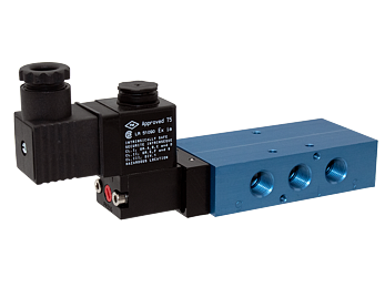




Compact Solenoid L Series Valves - Intrinsically Safe, Standard Temperature Applications -20 to 123 F (-29 to 50 C)
 Operating Instructions - Bottom Mount Valves
Operating Instructions - Top Mount Valves
Product Catalog - Explosion-Proof & Intrinsically Safe Compact L Series
Operating Instructions - Bottom Mount Valves
Operating Instructions - Top Mount Valves
Product Catalog - Explosion-Proof & Intrinsically Safe Compact L Series
- Compact Design - Balanced spool construction
- Solenoid Pilot - Pilot uses full air line pressure to shift the valve, Solenoid guaranteed against burnout
- Solenoid Coils - Intrinsically Safe
- Tapered Tee-Seal - Bidirectional tapered Tee-Seal eliminates sticking problems
- Tested Tough - proven reliable according to SAE specifications: rust & water injected every 864,000 cycles for 20-million cycle
- Manual Override - Allows the solenoid valve to be used manually in case of electrical failure, or for quick cycle testing
- External Pilot Supply - Easily field convertible to external pilot supply
Valves
The AV inline L20 series valves are directional control spool valves, designed for a wide range of fluid control applications, providing users with a space-saving and lightweight design. With both inline or manifold mount, the L20 series provide flexible options for mounting. The balanced spool construction allows ports to be plugged for 2 way or 3 way function, or restricted for inexpensive cylinder exhaust speed control. A wide variety of options and operators available.
Tapered Tee-Seal ........ Eats Dirt
Bidirectional tapered Tee-Seal eliminates sticking problems.
- Flexes to clean spool
- Mechanically Locked
- No Spiral Twist
- No Extrusion
- Air Line Sediment is Wiped Away
- Tested tough and proven reliable according to SAE specifications: Rust and water injected every 864,000 cycles for 20 million cycles.
Solenoid ... Guaranteed Against Burnout
Three-way pilot uses full air line pressure to shift the valve. The pilot is internally supplied when the pressure at port one is 35 to 150 PSIG (240 to 1030 kPa). The coil is hermetically sealed as an integral watertight molded unit. Intrinsically-safe and explosion-proof versions available. Push Non-Locking Override is standard. (Extended Turn and Turn-Locking available).
Unable to load products. Please try again.
loading...
loading...
Product Overview
The Automatic Valve Compact L20 Series Solenoid Valves with Intrinsically Safe (IS) coils are directional control spool valves designed for pneumatic systems in classified hazardous locations where intrinsic safety is the preferred or specified protection method. These valves use solenoid coils certified Ex ia Class I, Groups A, B, C, D; Class II, Groups E, F, G; Class III, Division 1, Temperature Class T5, providing the same area coverage as explosion-proof designs while limiting circuit energy to levels that cannot ignite a flammable atmosphere under normal or single-fault conditions.
The intrinsically-safe coil and connector assembly (model A7106-374-DB) operates exclusively at 24 VDC and draws 1.6 watts in holding, significantly lower than the 4.5-watt standard solenoid coil. This low power level is fundamental to intrinsic safety: the reduced energy in the field wiring circuit cannot create a spark or thermal surface capable of igniting the surrounding atmosphere, even if a wire is broken, shorted, or the solenoid is damaged. The required A7106-374 Intrinsic Safety Barrier must be installed in the safe (non-classified) area to limit the circuit energy to certified intrinsically safe levels.
The L20 series balanced spool construction incorporates the Automatic Valve Tapered Tee-Seal, a bidirectional sealing element that is mechanically locked to prevent spiral twist and extrusion, flexes to clean the spool with every stroke, and wipes air line sediment from the sealing surface. This design has been validated to 20 million cycles per SAE test specifications with rust and water injection every 864,000 cycles, ensuring dependable service in the harsh process environments where intrinsically safe controls are most commonly applied.
Standard temperature operation from -20 to 123 F (-29 to 50 C) covers the ambient range for the majority of process plant, chemical, and oil and gas applications in temperate climates. The balanced spool design allows ports to be plugged for 2-way or 3-way function, and multiple valve functions including 5/2-way single solenoid, 5/2-way double solenoid, and 5/3-way center configurations provide comprehensive pneumatic circuit coverage.
Key Engineering Features
- Intrinsically Safe (Ex ia) Certification - Solenoid coil certified Ex ia Class I Groups A, B, C, D; Class II Groups E, F, G; Class III Div. 1 Temperature Class T5. Intrinsic safety limits circuit energy in the hazardous area to levels that cannot ignite a flammable atmosphere under normal or single-fault conditions, the highest protection level for electrical equipment.
- Ultra-Low Power Consumption - 1.6 Watts - The intrinsically-safe coil operates at 1.6 watts (holding), compared to 4.5 watts for standard solenoid coils. This reduced power level is fundamental to the intrinsic safety protection method and enables battery-powered and solar-powered remote applications.
- 24 VDC Operation - The intrinsically-safe coil operates exclusively on 24 VDC, compatible with standard industrial PLC output cards and Zener barrier/galvanic isolator IS interfaces common in process automation and DCS systems.
- Coil and Connector Included - The A7106-374-DB intrinsically-safe coil and connector assembly is included with the valve, eliminating a separate ordering step and ensuring the correct matched IS coil/connector system is supplied.
- IS Barrier Required in Safe Area - The A7106-374 Intrinsic Safety Barrier must be installed in the safe area (non-classified zone) between the PLC/controller output and the IS coil field wiring. The barrier limits the voltage, current, and power available in the hazardous area wiring under fault conditions.
- Tapered Tee-Seal Technology - Bidirectional Tapered Tee-Seal is mechanically locked, flexes to clean the spool, eliminates spiral twist and extrusion, and wipes sediment away from sealing surfaces. SAE-validated to 20 million cycles with rust and water injection every 864,000 cycles.
- Balanced Spool Construction - Balanced spool design allows port plugging for 2-way or 3-way function and port restriction for cylinder speed control, reducing BOM complexity for applications with multiple circuit configurations.
- Push Non-Locking Manual Override - Standard push non-locking override allows manual valve actuation for commissioning and verification without defeating the intrinsic safety classification or introducing energy sources into the classified area.
- Inline and Manifold Mounting - Supports both inline pipe mounting and bottom manifold mounting for consolidating multiple valves on a single assembly.
- Field-Convertible External Pilot Supply - Easily field convertible to external pilot supply (Option B) for vacuum-to-35 PSIG inlet applications or independent pilot and working pressure circuits.
Technical Specifications
General Specifications
| Parameter | Specification |
| Series | L20 (Compact Spool Valve) |
| Valve Type | Directional Control Spool Valve |
| Application | Intrinsically Safe - Hazardous Locations |
| IS Classification | Ex ia Class I Groups A, B, C, D; Class II Groups E, F, G; Class III Div. 1, T5 |
| Valve Functions Available | 5/2-Way Single Solenoid (Spring Return); 5/2-Way Double Solenoid (Detented); 5/3-Way Double Solenoid (Closed Center, Open Center, Pressure Center) |
| Port Sizes | 1/4 NPT; 3/8 NPT (G/BSPP available as Option W) |
| Port Thread Standard | NPT standard; G (BSPP) available as option |
| Construction | Balanced Spool with Tapered Tee-Seal |
| Flow Media | Filtered Air or Inert Gas (50 micron filtration or better) |
| Mounting | Inline; Manifold (Bottom Mount) |
| Body Material | Aluminum |
| Seal Material | Treated Buna-N (NBR) standard; Fluoroelastomer (FPM/FKM) available as Option A |
| Spool Material | Aluminum |
| Manual Override | Push Non-Locking (standard); Push Turn-Locking (Option 1); Extended Turn-Locking (Option 2); No Override (Option 4) |
| Pilot Supply | Internal (standard); External (Option B) |
| IS Barrier Required | A7106-374 Intrinsic Safety Barrier (not included, must be ordered separately) |
| Duty Rating | Continuous Duty |
Temperature Ratings
Standard temperature configuration uses Treated Buna-N (NBR) seals. Fluoroelastomer seals (Option A) are available for chemical resistance but do not change the temperature range. For low-temperature applications down to -40 F (-40 C), order the Intrinsically Safe Low Temperature series (Series 2994).
| Configuration | Ambient Temperature | Media Temperature |
| Standard (Buna-N seals) | 20 to 123 F (-29 to 50 C) | 20 to 123 F (-29 to 50 C) |
| With Fluoroelastomer Seals (Option A) | 20 to 123 F (-29 to 50 C) | 20 to 123 F (-29 to 50 C) |
| IS Coil Temperature Class | T5 (max surface 100 C / 212 F) | Not to exceed ambient limit |
Important: For applications below 40 F (4 C), compressed air must be dry (low dew point) to prevent ice formation in the valve spool. For ambient temperatures below -20 F (-29 C), order the Low Temperature Intrinsically Safe series (2994) rated to -40 F (-40 C).
Electrical Data (Solenoid Pilot Valves)
The intrinsically-safe coil operates at 24 VDC only. Power consumption is 1.6 watts, significantly lower than standard solenoid coils. The A7106-374 Intrinsic Safety Barrier is required in the safe area and is not included with the valve. The A7106-374-DB coil and connector assembly is included.
| Voltage | Power Consumption |
| 24 VDC (only) | 1.6 W (holding, IS coil) |
| Standard Coil Reference - 24 VDC | 4.8 W (standard coil, non-IS) |
| Low Watt Coil - 24 VDC (Option L) | 2.5 W (standard coil, non-IS) |
Electrical Connection Options
| Connection Type | Coil Code |
| Intrinsically-Safe Coil and Connector Assembly A7106-374-DB (included) | V (Operator Code) |
| IS Barrier A7106-374 (required in safe area, not included) | External Component |
| DIN 43650 Form B (for non-IS weather-proof coil, reference only) | W |
| Explosion-Proof Conduit (CSA/FM, reference only) | Y |
| ATEX Explosion-Proof 3m Cable (reference only) | Z |
Flow Performance Data
Flow performance data for L20 Series solenoid-operated directional control valves. 5/3-way center functions have reduced Cv due to the center-position flow path configuration. The IS coil is compatible with all L20 Series body sizes.
| Series | Port Size | Flow 5/2 (Cv) | Flow 5/2 (Nl/min) | Flow 5/3 (Cv) | Flow 5/3 (Nl/min) | Weight (valve only) |
| L07 | 1/8 NPT | 0.7 | 690 | 0.5 | 538 | 0.6 lb (0.27 kg) |
| L20 | 1/4 NPT | 1.8 | 1770 | 1.4 | 1381 | 0.9 lb (0.5 kg) |
| L20 | 3/8 NPT | 1.8 | 1770 | 1.4 | 1381 | 0.9 lb (0.5 kg) |
| L65 | 3/4 NPT | 9.0 | 8860 | 7.0 | 6911 | 3.5 lb (1.6 kg) |
| L65 | 1 NPT | 9.5 | 9350 | 7.4 | 7293 | 3.5 lb (1.6 kg) |
Response Time Formula: Operating pressure for standard 2-position valves: 35 to 150 PSIG (240 to 1030 kPa) at inlet port. 3-position valves require 50 to 150 PSIG (345 to 1030 kPa). External pilot option (B) extends inlet range to vacuum-to-35 PSIG with external pilot at 35 to 150 PSIG.
Certifications & Compliance
| Certification/Standard | Detail |
| Intrinsically Safe (Ex ia) | Ex ia Class I Division 1 Groups A, B, C, D; Class II Division 1 Groups E, F, G; Class III Div. 1. Temperature Class T5 (maximum surface temperature 100 C / 212 F). Coil part number A7106-374-DB. |
| IS Protection Level | Ex ia (intrinsically safe, level 'a') is the highest intrinsic safety protection level, meaning the circuit remains safe under two simultaneous faults in addition to normal operation. This exceeds Ex ib (one fault) protection. |
| Required IS Barrier | A7106-374 Intrinsic Safety Barrier must be installed in the safe area. The barrier limits the available energy in the field circuit to certified safe levels by clamping voltage and limiting current through Zener diodes or galvanic isolation. |
| CE Marking | CE conformity per applicable EU directives for export and use in European Union markets. |
| SAE Durability Testing | 20 million cycle test with rust and water injection every 864,000 cycles per SAE protocol, confirming mechanical reliability in contaminated and harsh environments. |
| Continuous Duty Rating | The IS coil is rated for 100% continuous energized duty at 24 VDC and 1.6 watts. |
Typical Applications & Industries
Oil and Gas Upstream and Midstream
- Wellhead and production facility pneumatic actuator controls in Class I Division 1 areas where intrinsic safety is specified by safety engineers as the preferred protection method for remote, unmanned, or battery-powered installations.
- Pipeline SCADA-controlled valve automation where 24 VDC IS circuits integrate directly with RTU (Remote Terminal Unit) and field transmitter IS barriers in existing IS power distribution architectures.
- Gas gathering and compression station pneumatic directional valve controls where intrinsic safety reduces equipment weight and complexity versus conduit-based explosion-proof installations in offshore or remote locations.
- Tank farm and bulk liquid terminal pneumatic valve sequencing where IS protection is preferred for its inherent simplicity: no conduit seals, no spark-ignition risk under fault, and compatibility with existing IS wiring infrastructure.
Chemical Process and Fine Chemical Manufacturing
- Continuous process reactor pneumatic valve controls in chemical plants where DCS (Distributed Control System) IS output modules interface directly with IS field devices through standard IS barriers without requiring explosion-proof enclosures.
- Specialty chemical batch process automation where frequent valve cycling and the need for reliable failure-mode behavior (spring return or last position) drive IS solenoid valve selection.
- Solvent handling and dispensing systems where IS protection eliminates the need for expensive explosion-proof conduit runs, reducing installation cost significantly in multi-valve installations.
- Gas detection system integration where IS pneumatic safety valves are controlled by SIL-rated gas detection and emergency shutdown systems via IS interfaces.
Pharmaceutical and Biotechnology Processes
- Solvent-based API (active pharmaceutical ingredient) synthesis process valve controls where IS protection is specified by process safety management programs for classified manufacturing areas.
- IBC (intermediate bulk container) filling and dispensing systems handling flammable solvents, where IS pneumatic valves controlled through validated IS barriers satisfy 21 CFR Part 11 and GAMP 5 requirements.
- Pilot plant and laboratory-scale process automation where the low power consumption of IS solenoid valves enables safe operation in portable or bench-scale installations with limited power supplies.
Marine and Offshore Platform Applications
- FPSO (Floating Production Storage and Offloading) vessel process area pneumatic valve controls where IS protection is standard practice due to cable routing constraints, explosion-proof conduit cost, and weight considerations.
- Offshore platform drilling and process module pneumatic directional valve automation where IS field devices minimize installation weight and eliminate conduit sealing requirements.
- Marine terminal loading arm and ship-shore interface pneumatic valve controls in areas classified for flammable vapor exposure, where IS low-energy circuits reduce ignition risk during berthing operations.
Power Generation and Utilities
- Coal-fired power plant fuel handling and coal conveying system pneumatic valve controls in Class II dust-classified areas where IS protection covers the combustible coal dust environment.
- Biogas and landfill gas power plant pneumatic actuator controls in methane-classified areas where IS low-power circuits are compatible with low-voltage DC power systems common in renewable energy installations.
- Gas turbine fuel system pneumatic valve automation where IS classification satisfies both the gas hazard (Class I Group D) and the reliability requirements for turbine trip and fuel shutoff valves.
Semiconductor and Electronics Fabrication
- Specialty gas process cabinet pneumatic valve controls in semiconductor fab environments where IS protection is specified for valves handling flammable specialty gases including silane, hydrogen, and diborane in classified gas cabinet zones.
- Solvent cleaning and etching process pneumatic valve sequencing in semiconductor manufacturing areas where solvent vapors create Class I Division 1 classified atmospheres inside process tools.
- Battery manufacturing and electrolyte handling pneumatic valve controls where flammable electrolyte solvents create classified areas requiring intrinsically safe or explosion-proof rated controls.
Ordering and Model Number Configuration
Automatic Valve L Series intrinsically-safe compact spool valves use the standard L Series model number with the V operator code designating the intrinsically-safe solenoid. The IS coil and connector (A7106-374-DB) are included. The A7106-374 IS barrier must be ordered and installed separately in the safe area.
|
Model Number Example: L2003GAVR-DB
L20 Series (L07=1/8-1/4 port; L20=1/4-3/8 port; L65=3/4-1 port)
0 Body Type (0 = Inline / Manifold)
3 Port Size (2=1/8", 3=1/4", 4=3/8", 6=3/4", 7=1")
G Function (G=3/2 Way NC; H=3/2 Way NO) - 3/2 Function Example or (A=5/2 single; B=5/2 double; C=5/3 block; D=5/3 exhaust; E=5/3 pressure)
A Body Design (A=Single; B=Double body)
V Operator 1 (V = Intrinsically-Safe Solenoid, 24 VDC only)
R Operator 2 (R=Spring Return; M=Detented; V=Center Operator)
DB Voltage Code (DB = 24 VDC only for IS coil)
Note: IS coil and connector assembly A7106-374-DB is included with valve. IS Barrier A7106-374 must be ordered separately and installed in safe area. Intrinsically-Safe operation is 24 VDC only. |
The intrinsically-safe coil operates at 24 VDC only. Voltage code DB must be specified for all IS valve orders.
The A7106-374-DB intrinsically-safe coil and connector assembly is included with the valve at no additional cost.
The A7106-374 Intrinsic Safety Barrier is not included and must be ordered separately. The barrier is a critical safety component; the valve must not be operated without a properly rated IS barrier in the safe area circuit.
For G (BSPP) metric thread connections, add Option W to the model number. This does not affect IS coil specifications.
Fluoroelastomer (FPM/FKM) seal Option A provides enhanced chemical resistance for applications involving petroleum-based media or aggressive fluid exposure.
External pilot supply Option B is available for applications where inlet pressure falls below 35 PSIG or vacuum inlet circuits are required.
Model number suffix -DB is mandatory for IS coil specification. All other voltage codes (DA, AA, AB) are for standard (non-IS) coil configurations only.
Key Model Number Examples - Intrinsically Safe
| Model Number | Description |
| L2003GAVR-DB | L20, 1/4 NPT, 3/2-Way NC, Single IS Solenoid, Spring Return, 24 VDC IS |
| L2003GBVV-DB | L20, 1/4 NPT, 3/2-Way NC, Double IS Solenoid, Detented, 24 VDC IS |
| L2003DBVDV-DB | L20, 1/4 NPT, 5/3-Way Open Center, Double IS Solenoid, 24 VDC IS |
| L2003ABVV-DB | L20, 1/4 NPT, 5/2-Way Double IS Solenoid, Detented, 24 VDC IS |
| L0703CBVDV-DB | L07, 1/4 NPT, 5/3-Way Closed Center, Double IS Solenoid, 24 VDC IS |
IS Coil vs. Standard Coil Power Comparison
| Coil Type | Voltage | Power (W) | Barrier Required |
| Intrinsically-Safe (V) | 24 VDC only | 1.6 W | Yes - A7106-374 |
| Standard Weather-Proof (W) | 12/24 VDC, 120/240 VAC | 4.8 W DC / 6.9 VA AC | No |
| Explosion-Proof CSA/FM (Y) | 12/24 VDC, 120/240 VAC | 4.8 W DC / 6.9 VA AC | No |
| ATEX Explosion-Proof (Z) | 12/24 VDC, 120/240 VAC | 4.8 W DC / 6.4 VA AC | No |
Accessories
Intrinsic Safety Barrier - A7106-374
The A7106-374 Intrinsic Safety Barrier is a required safe-area component for all intrinsically-safe L Series valve installations. The barrier mounts in the safe area (non-classified zone) between the 24 VDC power supply/PLC output and the IS field wiring. It limits the available energy in the hazardous area circuit through Zener diode energy clamps, ensuring the voltage, current, and power in the field circuit remain below the certified intrinsically safe thresholds under any fault condition. Contact Automatic Valve for barrier specifications and selection guidance.
Warning: The A7106-374 IS Barrier is NOT included with the valve. Operation of the intrinsically-safe solenoid coil without the properly rated IS barrier in the safe area circuit voids the intrinsic safety certification and may create an ignition hazard in the classified location.
Manifolds for L20 Series
Aluminum manifolds for L20 Series provide common inlet and common exhaust ports with top cylinder ports. Multiple IS-coil valves can be installed on a single manifold for consolidated control panel arrangements. Seals and mounting hardware are included.
| Series | Stations | Model Number | Port Size |
| L20 | 2 | A8020-002 | 3/8 |
| L20 | 4 | A8020-004 | 3/8 |
Related Products & Accessories
- Compact L Series - Intrinsically Safe, Low Temperature - L20 Series compact spool valves with intrinsically-safe coils rated to -40 F (-40 C) for hazardous location cold-weather applications including cold storage, outdoor installations, and arctic environments. https://www.automaticvalve.com/series/2994-compact-solenoid-l-series-valves-intrinsically-safe-low-temperature-applications
- Compact L Series - CSA/FM Explosion-Proof, Standard Temperature - L20 Series compact spool valves with CSA/FM explosion-proof coils for Class I Division 1 hazardous locations where explosion-proof (rather than IS) protection is specified. https://www.automaticvalve.com/series/2980-compact-solenoid-l-series-valves-csafm-standard-temperature-applications
- Compact L Series - ATEX Explosion-Proof, Standard Temperature - L20 Series compact spool valves with ATEX explosion-proof coils for Zone 1 and Zone 21 hazardous locations in European and international markets. https://www.automaticvalve.com/series/2982-compact-solenoid-l-series-valves-atex-standard-temperature-applications
- Compact L Series - Standard Temperature (Non-Hazardous) - L20 Series compact spool valves with weather-proof solenoid coils for general automation in non-classified environments, providing the same spool platform without hazardous location rated coils. https://www.automaticvalve.com/series/2979-compact-solenoid-l-series-valves-standard-temperature-applications
- L Series Manifolds - Multi-station aluminum manifolds compatible with L07 and L20 IS series valves, enabling consolidated manifold-mounted IS valve banks in control panels or field junction enclosures. https://www.automaticvalve.com
- Automatic Valve Documentation Library - Complete documentation for L Series compact spool valves including IS coil certification documents, dimensional drawings, and the IS barrier selection guide. https://www.automaticvalve.com/documents
Frequently Asked Questions (FAQ)
Q: What is intrinsic safety and how does it differ from explosion-proof protection?
A: Intrinsic safety (Ex ia) is an electrical protection method that prevents ignition by limiting the energy available in the hazardous area circuit to levels too low to ignite a flammable atmosphere, even under fault conditions including wire breaks and short circuits. Explosion-proof (Ex d) contains any internal ignition within a robust enclosure designed to withstand the explosion pressure without propagating flame. Intrinsic safety is inherently safer because it prevents ignition rather than containing it, allows lighter-weight wiring and smaller conduit, and is the only protection method that remains safe with open wiring in the classified area during troubleshooting. The trade-off is that IS requires an external barrier and is limited to low-power loads like solenoid valves.
Q: Why is the A7106-374 Intrinsic Safety Barrier required?
A: The IS barrier is the critical safe-area component that limits the voltage, current, and power available to the IS coil in the hazardous area. Without the barrier, the full energy of the 24 VDC power supply is available at the coil, which can create sparks under fault conditions sufficient to ignite a flammable atmosphere. The barrier uses Zener diodes to clamp voltage and series resistors to limit current, ensuring the field circuit energy never exceeds the certified intrinsically safe thresholds. The A7106-374 barrier must be installed in the non-classified safe area, typically in the control panel, marshaling cabinet, or DCS I/O room.
Q: What voltage does the intrinsically-safe solenoid operate on?
A: The intrinsically-safe coil operates exclusively on 24 VDC. No other voltage options (AC voltages, 12 VDC, 125 VDC) are available for the IS configuration. This 24 VDC requirement is compatible with standard industrial PLC output cards, DCS AI cards, and most IS barriers, which are designed for 24 VDC NAMUR or digital IS field devices.
Q: What is the power consumption of the IS coil compared to standard solenoid coils?
A: The intrinsically-safe coil draws 1.6 watts in holding, compared to 4.8 watts for the standard solenoid coil. This 70% power reduction is fundamental to achieving intrinsic safety certification: lower energy in the circuit means lower risk of ignition under fault conditions. The low power consumption also enables applications powered by limited energy sources such as solar power systems, battery backup panels, and UPS systems used in remote unmanned locations.
Q: What hazardous groups does the IS classification cover?
A: The IS coil certification covers Class I, Groups A (acetylene), B (hydrogen), C (ethylene), and D (most hydrocarbons); Class II, Groups E (metal dusts), F (coal and carbonaceous dusts), and G (grain and agricultural dusts); and Class III (ignitable fibers). This comprehensive group coverage satisfies the electrical area classification requirements for the vast majority of oil and gas, chemical, pharmaceutical, and industrial applications in North America.
Q: Can IS and explosion-proof protection be used interchangeably?
A: Both IS and explosion-proof (CSA/FM or ATEX) protection methods are acceptable for Class I Division 1 (or Zone 1) classified areas. The choice between them is made based on system architecture, installation method, available power, and operational preference. IS is preferred when: existing IS barriers are already installed in the safe area; lightweight or portable equipment is needed; cable runs are long and conduit cost is high; or maintenance is performed without gas-freeing the area. Explosion-proof is preferred when: higher power is needed than IS allows; standard industrial power supplies without barriers are used; or AC voltage operation is required.
Q: What operating pressure is required?
A: For standard 2-position configurations (5/2-way), the operating pressure at the inlet port is 35 to 150 PSIG (240 to 1030 kPa). For 3-position configurations (5/3-way), the minimum pressure increases to 50 PSIG (345 kPa). External pilot supply Option B extends the inlet range to vacuum-to-35 PSIG with independent pilot supply at 35 to 150 PSIG.
Q: What is the Cv and flow capacity of the IS L20 valve?
A: The intrinsically-safe coil does not change the hydraulic performance of the valve body. The L20 Series achieves Cv 1.8 (1770 Nl/min) for 5/2-way configurations and Cv 1.4 (1381 Nl/min) for 5/3-way configurations at 1/4 and 3/8 NPT port sizes. The L07 Series (1/8 NPT) delivers Cv 0.7, and the L65 Series (3/4 and 1 NPT) achieves Cv up to 9.5.
Q: Can the IS coil be connected directly to a PLC output without the barrier?
A: No. Connecting the IS coil directly to a PLC output or power supply without the A7106-374 IS barrier defeats the intrinsic safety protection and invalidates the area classification compliance. The barrier must be in the circuit between any non-IS power source and the IS field coil. Some PLCs with integrated IS output modules incorporate the barrier function internally; in this case, verify that the PLC IS module output parameters (Voc, Isc, Po) are compatible with the A7106-374-DB coil entity parameters before installation without a separate barrier.
Q: What filtration is required for the air supply?
A: Filtered air at 50 microns or better is required. The Tapered Tee-Seal provides contamination tolerance superior to conventional O-ring seals, but proper upstream filtration remains essential for achieving rated cycle life in high-cycle applications. A coalescing filter is recommended for systems with oil contamination or high moisture content.
Q: Are G (BSPP) threads available for international installations?
A: Yes. Adding Option W to the model number specifies G (BSPP) threads compatible with ISO 228-1 metric fittings used in European and international pneumatic systems. All IS coil specifications remain unchanged.
Q: Can the IS valve be installed on a multi-station manifold?
A: Yes. The IS valve body is physically identical to the standard weather-proof version and mounts on the same L20 manifolds (A8020 series). Multiple IS valves can be manifolded together for control panel or junction box installations. Ensure that the combined IS circuit parameters of multiple valves connected to a single IS barrier are within the barrier's certified output parameter limits.
Q: What does the T5 temperature class mean for the IS coil?
A: Temperature Class T5 means the maximum surface temperature of the IS coil assembly does not exceed 100 C (212 F) under any operating condition within rated parameters. This establishes compatibility with all gases and vapors having auto-ignition temperatures above 100 C, covering essentially all industrial hydrocarbons and solvents. T5 is one of the most conservative temperature class ratings, providing a substantial safety margin against auto-ignition of typical process gases.
Installation & Maintenance Guidelines
- Install the A7106-374 Intrinsic Safety Barrier in the safe area (non-classified zone) before commissioning. The barrier must be mounted in the control panel, marshaling cabinet, or DCS room, connected between the 24 VDC power source and the IS field circuit.
- Verify that the IS barrier entity parameters (Voc, Isc, Po, Co, Lo) are compatible with the A7106-374-DB coil's entity parameters (Ui, Ii, Pi, Ci, Li) before energizing the circuit. Consult Automatic Valve for entity parameter documentation.
- Wire the hazardous area field circuit using IS-rated cable (blue sheath per IEC 60446 or labeled for IS use) from the barrier's field terminals to the IS coil connector in the classified area.
- Maintain separation between IS and non-IS wiring throughout the installation per IEC 60079-14 requirements to prevent inductive or capacitive coupling that could transfer energy into the IS circuit.
- Supply filtered air at 50 microns or finer upstream of the valve. Install a lockout/tagout-capable isolation valve upstream for maintenance access.
- Maintain operating pressure between 35 and 150 PSIG at the inlet for 2-position valves. 3-position valves require a minimum of 50 PSIG.
- Dry the compressed air supply to a low dew point if ambient temperatures may fall below 40 F (4 C) to prevent ice formation in the spool bore.
- Mount in any orientation. Inline mounting with the solenoid vertical is preferred for condensate drainage.
- Do not exceed 150 PSIG at any port.
- Use only petroleum-based lubricants with aniline point between 82 C and 99 C at approximately ISO 32 viscosity if lubricated air is used. Avoid phosphate-ester additives.
Warranty & Global Support
Automatic Valve provides a standard warranty covering defects in material and workmanship. Contact Automatic Valve directly for warranty terms applicable to intrinsically safe products.
Technical support is available through Automatic Valve's engineering team for IS application assistance, barrier selection, entity parameter verification, and replacement part identification. Contact: (248) 474-6761.
Automatic Valve is a ROSS Controls company. IS coil assemblies (A7106-374-DB), IS barriers (A7106-374), seal kits, and replacement parts are available for prompt shipment.
For IS coil entity parameters, barrier specifications, dimensional drawings, and certification documentation, visit automaticvalve.com or contact Automatic Valve at (248) 474-6761.
Product Catalog - L Series Hazardous Location Valves: https://www.automaticvalve.com/documents/6535/Hazardous_Locations_Valves_L_Series_AV-DCHL_L_EN.pdf
Service Instructions - Compact Inline Spool Valves: https://www.automaticvalve.com/documents/405/Compact_Inline_Valves_Service_Information_Form_AV-Compact-IL_OI.pdf
Download Documents
Compact Solenoid L Series Valves - Intrinsically Safe, Standard Temperature Applications