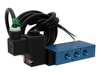




Compact Solenoid L Series Valves - ATEX, Standard Temperature Applications -20 to 123 F (-29 to 50 C)
 Operating Instructions - Bottom Mount Valves
Operating Instructions - Top Mount Valves
Product Catalog - Explosion-Proof & Intrinsically Safe Compact L Series
Operating Instructions - Bottom Mount Valves
Operating Instructions - Top Mount Valves
Product Catalog - Explosion-Proof & Intrinsically Safe Compact L Series
- Compact Design - Balanced spool construction
- Solenoid Pilot - Pilot uses full air line pressure to shift the valve, Solenoid guaranteed against burnout
- Solenoid Coils - Explosion-Proof ATEX Certified
- Tapered Tee-Seal - Bidirectional tapered Tee-Seal eliminates sticking problems
- Tested Tough - proven reliable according to SAE specifications: rust & water injected every 864,000 cycles for 20-million cycle
- Manual Override - Allows the solenoid valve to be used manually in case of electrical failure, or for quick cycle testing
- External Pilot Supply - Easily field convertible to external pilot supply
Valves
The AV inline L20 series valves are directional control spool valves, designed for a wide range of fluid control applications, providing users with a space-saving and lightweight design. With both inline or manifold mount, the L20 series provide flexible options for mounting. The balanced spool construction allows ports to be plugged for 2 way or 3 way function, or restricted for inexpensive cylinder exhaust speed control. A wide variety of options and operators available.
Tapered Tee-Seal ........ Eats Dirt
Bidirectional tapered Tee-Seal eliminates sticking problems.
- Flexes to clean spool
- Mechanically Locked
- No Spiral Twist
- No Extrusion
- Air Line Sediment is Wiped Away
- Tested tough and proven reliable according to SAE specifications: Rust and water injected every 864,000 cycles for 20 million cycles.
Solenoid ... Guaranteed Against Burnout
Three-way pilot uses full air line pressure to shift the valve. The pilot is internally supplied when the pressure at port one is 35 to 150 PSIG (240 to 1030 kPa). The coil is hermetically sealed as an integral watertight molded unit. Intrinsically-safe and explosion-proof versions available. Push Non-Locking Override is standard. (Extended Turn and Turn-Locking available).
loading...
loading...
Product Overview
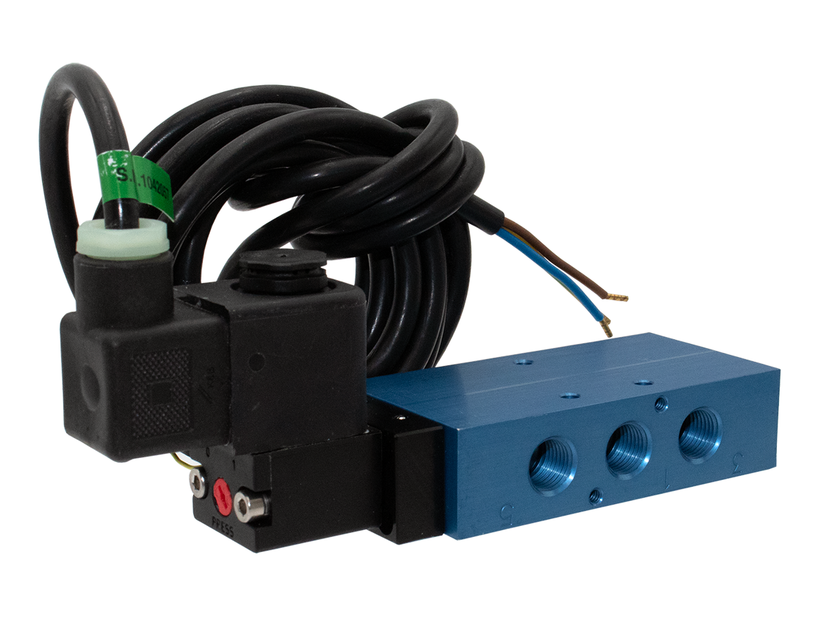
The Automatic Valve Compact L20 Series Solenoid Valves with ATEX certification are directional control spool valves designed for pneumatic systems in European and internationally classified hazardous locations. These valves combine the compact L20 spool platform with ATEX-certified explosion-proof solenoid coils rated Ex m II T5 (PTB 03 ATEX 2018 X), Ex II 2G EEx m II T5, and Ex II 2D IP65 T95 C, satisfying the requirements of the ATEX Directive 2014/34/EU for Category 2G (Zone 1) gas atmospheres and Category 2D (Zone 21) dust atmospheres. CE marking is provided in compliance with the EMF and Low Voltage Directives.
The L20 series balanced spool construction incorporates Automatic Valve's Tapered Tee-Seal, a bidirectional sealing element that is mechanically locked to prevent spiral twist and extrusion, flexes to clean the spool surface with every stroke, and wipes air line sediment away from the sealing interface. This design has been validated to 20 million cycles per SAE test specifications with rust and water injected every 864,000 cycles, ensuring long-term reliability in the process environments common to European chemical, pharmaceutical, and refining facilities.
The ATEX solenoid coil is supplied with a 3-meter cable and strain relief fitting as standard, accommodating the cable gland installation methods typical in IEC 60079-14 compliant wiring installations. The enclosure is rated IP65, protecting against ingress of dust and low-pressure water jets. Unlike the conduit-based CSA/FM design, the ATEX cable gland system eliminates the need for conduit sealing fittings and simplifies installation in European-standard electrical installations.
Available valve functions include 5/2-way single solenoid spring return, 5/2-way double solenoid detented, and 5/3-way double solenoid with closed center, open center, or pressure center configurations. Port sizes of 1/4 NPT and 3/8 NPT (G/BSPP available as Option W) serve the full range of cylinder and actuator connections found in process plant pneumatic circuits.
Key Engineering Features
- ATEX Certification - Zone 1 and Zone 21 - ATEX-certified solenoid coil rated Ex m II T5 (PTB 03 ATEX 2018 X), Ex II 2G EEx m II T5 (Zone 1 gas atmospheres), and Ex II 2D IP65 T95 C (Zone 21 dust atmospheres). Satisfies ATEX Directive 2014/34/EU Category 2G and 2D requirements.
- CE Marked for EU Market Compliance - CE conformity declaration per EMF Directive and Low Voltage Directive enables direct use in European Union member states without additional national approvals.
- 3-Meter Cable with Strain Relief - ATEX coil is supplied with 3 meters of armored cable and a strain relief fitting as standard, compatible with IEC 60079-14 wiring installation methods and standard European cable gland fittings.
- IP65 Coil Enclosure - IP65 ingress protection provides dust-tight sealing and resistance to low-pressure water jets, meeting the enclosure requirements for both Zone 1 gas and Zone 21 dust classified environments.
- Tapered Tee-Seal Technology - Bidirectional Tapered Tee-Seal is mechanically locked, flexes to clean the spool, eliminates spiral twist and extrusion, and wipes sediment from sealing surfaces. SAE-validated to 20 million cycles with rust and water injection.
- Balanced Spool Construction - Balanced spool design supports port plugging for 2-way or 3-way configurations and port restriction for cylinder exhaust speed control, reducing component count in multi-function pneumatic circuits.
- Full Air Line Pressure Pilot - Three-way solenoid pilot operates on full inlet air line pressure (35 to 150 PSIG / 240 to 1030 kPa), delivering positive shifting at all rated pressures without reduced-pressure pilot instability.
- Hermetically Sealed Coil - Solenoid coil is hermetically sealed as an integral watertight molded unit, guaranteed against burnout, rated for continuous duty, and resistant to chemical vapors common in process plant environments.
- Push Non-Locking Manual Override - Standard push non-locking override provides manual valve actuation for commissioning and testing without tools, without defeating the ATEX classification of the coil assembly.
- Field-Convertible External Pilot Supply - Easily field convertible to external pilot supply (Option B) for vacuum-to-35 PSIG inlet applications or circuits requiring independent pilot and working pressure.
Technical Specifications
General Specifications
| Parameter | Specification |
| Series | L20 (Compact Spool Valve) |
| Valve Type | Directional Control Spool Valve |
| Certification | ATEX Explosion-Proof; CE Marked |
| ATEX Classification | Ex m II T5 (PTB 03 ATEX 2018 X); Ex II 2G EEx m II T5 (Zone 1 Gas); Ex II 2D IP65 T95 C (Zone 21 Dust) |
| Valve Functions Available | 5/2-Way Single Solenoid (Spring Return); 5/2-Way Double Solenoid (Detented); 5/3-Way Double Solenoid (Closed Center, Open Center, Pressure Center) |
| Port Sizes | 1/4 NPT; 3/8 NPT (G/BSPP available as Option W) |
| Port Thread Standard | NPT standard; G (BSPP) available as option |
| Construction | Balanced Spool with Tapered Tee-Seal |
| Flow Media | Filtered Air or Inert Gas (50 micron filtration or better) |
| Mounting | Inline; Manifold (Bottom Mount) |
| Body Material | Aluminum (303 and 316 Stainless Steel available as options) |
| Seal Material | Treated Buna-N (NBR) standard; Fluoroelastomer (FPM/FKM) available as Option A |
| Spool Material | Aluminum |
| Manual Override | Push Non-Locking (standard); Push Turn-Locking (Option 1); Extended Turn-Locking (Option 2); No Override (Option 4) |
| Pilot Supply | Internal (standard); External (Option B) |
| Duty Rating | Continuous Duty |
| Coil Enclosure | IP65 |
| ATEX Cable | 3 meters with strain relief (standard) |
Temperature Ratings
Standard temperature configuration uses Treated Buna-N (NBR) seals. The ATEX coil temperature code T5 corresponds to a maximum surface temperature of 100 C (212 F). Operating temperature limits are determined by seal material selection.
| Configuration | Ambient Temperature | Media Temperature |
| Standard (Buna-N seals, ATEX Coil) | 20 to 123 F (-29 to 50 C) | 20 to 123 F (-29 to 50 C) |
| With Fluoroelastomer Seals (Option A) | 20 to 123 F (-29 to 50 C) | 20 to 123 F (-29 to 50 C) |
| High Temp Coil Option (CT) | 0 to 180 F (-18 to 82 C) | 0 to 180 F (-18 to 82 C) |
| ATEX Coil Maximum Surface Temperature | T5 Rating (max surface 100 C / 212 F) | T95 C for Zone 21 dust applications |
Important: For media temperatures below 40 F (4 C), the compressed air supply must be dry (low dew point) to prevent ice formation inside the valve spool bore.
Electrical Data (Solenoid Pilot Valves)
ATEX explosion-proof coils are rated for continuous duty at 100% energized cycle. The ATEX coil (Option Z) is supplied with a 3-meter cable and strain relief as standard. All coils are hermetically sealed against moisture and chemical vapors. Consult factory for non-standard voltages.
| Voltage | Power Consumption |
| 12 VDC | 4.8 W (inrush); 3.5 W (holding) |
| 24 VDC | 4.8 W (inrush); 3.5 W (holding) |
| 120 VAC, 50/60 Hz | 6.9 VA (inrush); 3.4 VA (holding) |
| 240 VAC, 50/60 Hz | 6.4 VA (inrush); 3.3 VA (holding) |
| 24 VDC (Low Watt Option L) | 2.5 W |
| 24 VDC (Lowest Watt Option LL) | 0.7 W |
Electrical Connection Options
| Connection Type | Coil Code |
| ATEX Explosion-Proof 3-Meter Cable with Strain Relief (Zone 1/21) | Z (Option) |
| DIN 43650 Form B (Weather-Proof, IP65, NEMA 4X) | W (Standard Solenoid) |
| 18" Flying Leads (Weather-Proof, NEMA 4X, Option G) | G |
| 1/2" Conduit with 30" Leads (Weather-Proof, Option C) | C |
| 1/2" Conduit High Temp Coil with 30" Leads (Option CT) | CT |
Flow Performance Data
Flow performance data for L20 Series solenoid-operated directional control valves. 5/3-way center position functions have reduced Cv due to the three-path flow configuration at center.
| Series | Port Size | Flow 5/2 (Cv) | Flow 5/2 (Nl/min) | Flow 5/3 (Cv) | Flow 5/3 (Nl/min) | Weight |
| L07 | 1/8 NPT | 0.7 | 690 | 0.5 | 538 | 0.6 lb (0.27 kg) |
| L20 | 1/4 NPT | 1.8 | 1770 | 1.4 | 1381 | 0.9 lb (0.5 kg) |
| L20 | 3/8 NPT | 1.8 | 1770 | 1.4 | 1381 | 0.9 lb (0.5 kg) |
| L65 | 3/4 NPT | 9.0 | 8860 | 7.0 | 6911 | 3.5 lb (1.6 kg) |
| L65 | 1 NPT | 9.5 | 9350 | 7.4 | 7293 | 3.5 lb (1.6 kg) |
Response Time Formula: Operating pressure for standard 2-position valves: 35 to 150 PSIG (240 to 1030 kPa) at inlet port. 3-position valves require 50 to 150 PSIG (345 to 1030 kPa). External pilot option (B) extends inlet range to vacuum-35 PSIG with external pilot at 35 to 150 PSIG.
Certifications & Compliance
| Certification/Standard | Detail |
| ATEX Directive 2014/34/EU | Explosion-proof coil certified under ATEX Directive for Category 2G (Zone 1, gas) and Category 2D (Zone 21, dust) equipment groups. Certification reference: PTB 03 ATEX 2018 X. |
| ATEX Gas Classification | Ex II 2G EEx m II T5. Group II (non-mining), Category 2G (Zone 1), Ex m (molded/encapsulated) protection, Temperature Class T5 (maximum surface temperature 100 C / 212 F). |
| ATEX Dust Classification | Ex II 2D IP65 T95 C. Group II (non-mining), Category 2D (Zone 21), IP65 enclosure, Maximum surface temperature 95 C for dust applications. |
| CE Marking | CE conformity per EMF Directive and Low Voltage Directive. CE declaration of conformity available for EU market entry and Machinery Directive compliance documentation. |
| Notified Body Certification | PTB (Physikalisch-Technische Bundesanstalt) issued certification 03 ATEX 2018 X, one of Europe's most recognized notified bodies for ATEX equipment certification. |
| IP65 Enclosure Rating | Coil enclosure provides complete protection against contact with dust (IP6X) and resistance to low-pressure water jets from any direction (IPX5), as defined by IEC 60529. |
| SAE Durability Validation | 20 million cycle test with rust and water injection every 864,000 cycles per SAE protocol, confirming mechanical reliability in contaminated environments. |
Typical Applications & Industries
European Chemical and Specialty Chemical Manufacturing
- Batch reactor and continuous process valve sequencing in ATEX Zone 1 classified areas handling flammable solvents including toluene, xylene, acetone, and methanol per ATEX Category 2G requirements.
- Bulk chemical storage terminal loading arm automation and tank inlet/outlet valve controls in ATEX Zone 1 areas adjacent to flammable liquid storage.
- Distillation and solvent recovery unit pneumatic actuator controls in chemical plants where vapor cloud zones require Zone 1 or Zone 2 classification under EN 60079-10-1.
- Polymer and resin manufacturing process controls in plants handling styrene, acrylates, and vinyl chloride monomers, all of which create Zone 1 classifications in production areas.
European Oil Refining and Petrochemical
- Crude oil processing unit directional valve controls in ATEX Zone 1 areas adjacent to atmospheric and vacuum distillation columns where hydrocarbon vapors are continuously present.
- LNG (liquefied natural gas) terminal and regasification facility pneumatic valve controls where methane Group IIC classifications and Zone 1 area designations apply.
- Platforming, hydrocracking, and catalytic reforming unit valve automation where hydrogen-rich gas streams create Group IIC Zone 1 hazardous area classifications.
- Offshore platform topside process area pneumatic directional valve controls where ATEX Zone 1 and Zone 2 classifications cover the majority of the production deck.
Pharmaceutical Manufacturing (ATEX Classified Areas)
- API synthesis reactor area pneumatic valve controls in European pharmaceutical plants where flammable solvent concentrations create ATEX Zone 1 conditions during filling, emptying, and sampling operations.
- Solvent extraction, recrystallization, and purification process valve sequencing in pharmaceutical production suites requiring ATEX Zone 1 rated pneumatic components.
- Tablet coating and spray drying pneumatic valve automation in areas classified Zone 1 or Zone 2 due to alcohol and solvent-based coating solutions.
Food, Beverage, and Brewing with Flammable Dust Classification
- Grain milling and flour processing pneumatic conveying system diverter valves in ATEX Zone 21 classified areas where suspended grain dust creates explosive atmosphere conditions per EN 60079-10-2.
- Sugar refinery and confectionery plant pneumatic actuator controls in dust-classified zones (ATEX Category 2D) around sugar handling, conveying, and packaging equipment.
- Brewing and distillery pneumatic valve automation in ATEX Zone 2 areas adjacent to fermentation vessels and spirit storage where alcohol vapor concentrations may occur during normal operations.
Wastewater Treatment and Biogas
- Anaerobic digester biogas (methane and CO2 mixture) handling area pneumatic valve controls in European wastewater treatment plants requiring ATEX Zone 1 classification in gas headspace areas.
- Biogas upgrading and biomethane injection station pneumatic actuator controls where methane concentrations create ATEX Zone 1 conditions inside enclosed processing buildings.
- Sludge handling and dewatering facility pneumatic valve automation in areas with potential for explosive methane accumulation requiring ATEX Category 2G equipment.
Mining and Tunneling (Surface and Underground)
- European coal and potash mine surface facility pneumatic valve controls in ATEX Zone 21 dust-classified areas around processing, conveying, and loading equipment.
- Tunneling equipment pneumatic actuator controls in underground environments where explosive gas pockets may be encountered during excavation, requiring ATEX Group II Category 2G equipment.
- Aggregate and mineral processing plant pneumatic valve automation in ATEX Zone 22 dust-classified areas around crushers, screens, and conveyors handling combustible mineral dusts.
Ordering and Model Number Configuration
Automatic Valve L Series compact spool valves use a structured model number system. The example below shows the ATEX-certified explosion-proof variant ordering structure for an L20 Series valve with 1/4 NPT ports.
|
Model Number Example: L2003AAWR-DBZ
L20 Series (L07=1/8-1/4 port; L20=1/4-3/8 port; L65=3/4-1 port)
0 Body Type (0 = Inline / Manifold)
3 Port Size (2=1/8", 3=1/4", 4=3/8", 6=3/4", 7=1")
A Function (A=5/2 single 2-pos; B=5/2 double 2-pos; C=5/3 block center; D=5/3 exhaust center; E=5/3 pressure center)
A Body Design (A=Single; B=Double body)
W Operator 1 (W=Weather-Proof Solenoid; V=Intrinsically-Safe; A=Air Pilot; F=Hand Lever; I=Palm Button; K=Foot Pedal; L=Lockout)
R Operator 2 (R=Spring Return; M=Detented; V=Center Operator)
DB Voltage Code (DA=12VDC or 24VAC; DB=24VDC; AA=120VAC/60Hz; AB=240VAC/60Hz)
Z Option Code (Z=Explosion-Proof ATEX; Y=Explosion-Proof CSA/FM; B=External Pilot; A=Fluoroelastomer Seals; W=G/BSPP Threads; C=Conduit Coil; CT=Conduit High Temp; G=18" Leads; L=Low Watt; 1=Turn-Locking Override; 4=No Override) |
ATEX explosion-proof coils (Option Z) are supplied with a 3-meter cable and strain relief fitting as standard. Coil part number 7152-9** with ** representing the voltage code.
The ATEX coil (Option Z) is certified PTB 03 ATEX 2018 X. The full ATEX marking on the coil reads: Ex m II T5 and Ex II 2G EEx m II T5 / Ex II 2D IP65 T95 C.
For G (BSPP) metric thread connections, add Option W to the model number. This is recommended for installations where European pipe fittings (EN ISO 228-1) are used.
Fluoroelastomer (FPM/FKM) seal Option A provides enhanced chemical resistance. Required for applications involving petroleum-based media, aromatic solvents, or chlorinated compounds. Standard Buna-N (NBR) seals are compatible with most aliphatic hydrocarbons and aqueous media.
External pilot supply Option B is required for applications where inlet pressure falls below 35 PSIG or where vacuum-to-pressure circuits are used.
Low-watt coil Option L (2.5 W) and lowest-watt Option LL (0.7 W, 24 VDC only with Type 2 override) are available for general automation variants. Consult factory for availability with ATEX coil option Z.
Voltage Code Reference
| Voltage Code | Voltage | Power (W/VA) |
| DA | 12 VDC | 4.8 W DC |
| DB | 24 VDC | 4.8 W DC |
| AA | 120 VAC, 50/60 Hz | 6.9 VA AC |
| AB | 240 VAC, 50/60 Hz | 6.4 VA AC |
| AB | 125 VDC | 5.9 W DC |
Key Model Number Examples - ATEX Explosion-Proof
| Model Number | Description |
| L2003AAWR-DBZ | L20, 1/4 NPT, 5/2 Single Solenoid, Spring Return, 24 VDC, ATEX Explosion-Proof |
| L2003ABWW-DBZ | L20, 1/4 NPT, 5/2 Double Solenoid, Detented, 24 VDC, ATEX Explosion-Proof |
| L2004AAWR-DBZ | L20, 3/8 NPT, 5/2 Single Solenoid, Spring Return, 24 VDC, ATEX Explosion-Proof |
| L2003AAWR-AAZ | L20, 1/4 NPT, 5/2 Single Solenoid, Spring Return, 120 VAC/60 Hz, ATEX Explosion-Proof |
| L2003CBWDW-DBZ | L20, 1/4 NPT, 5/3 Closed Center, Double Solenoid, 24 VDC, ATEX Explosion-Proof |
ATEX Coil Weight Reference
| Coil Type | Weight kg | Weight lb |
| Weather-Proof (W) | 0.05 | 0.12 |
| Explosion-Proof CSA/FM (Y) | 0.20 | 0.44 |
| ATEX Explosion-Proof (Z) | 0.36 | 0.78 |
| Intrinsically-Safe (V) | 0.21 | 0.46 |
Accessories
Manifolds for L20 Series
Aluminum manifolds for L20 series provide common inlet and common exhaust ports with top cylinder ports. Valve mounting screws attach from the bottom. Available in 2 through 10 station configurations for consolidating multiple L20 valves on a single manifold assembly. Seals and mounting hardware are included.
| Series | Stations | Model Number | Port Size |
| L20 | 2 | A8020-002 | 3/8 |
| L20 | 4 | A8020-004 | 3/8 |
DIN 43650 Electrical Connectors (Weather-Proof Coil Only)
DIN 43650 Form B connectors for use with weather-proof solenoid coils. Note: ATEX explosion-proof coils (Option Z) are supplied with an integrated 3-meter cable and do not accept field-installed DIN connectors. Connectors below apply to standard weather-proof (W) coil configurations only.
| Connector Model | Type | Voltage Range |
| 7020-001 | Strain Relief, No Cord | 100-240 VAC / 48-120 VDC |
| 7020-AA | Strain Relief with Indicator Light | 6-48 VAC/VDC |
| 7020-DB | 1/2" Conduit, No Cord | 100-240 VAC / 48-120 VDC |
| 7039-001 | Molded with 6-ft Cord | 100-240 VAC / 48-120 VDC |
Warning: Do not substitute weather-proof DIN connectors (7020 series) on ATEX explosion-proof coils (Option Z). The 3-meter cable with strain relief supplied with the ATEX coil is integral to the explosion-proof protection and must not be replaced or bypassed.
Related Products & Accessories
- Compact L Series - CSA/FM Explosion-Proof, Standard Temperature - L20 Series compact spool valves with CSA/FM explosion-proof certified coils for Class I Division 1 hazardous locations per North American NEC/CEC classifications. https://www.automaticvalve.com/series/2980-compact-solenoid-l-series-valves-csafm-standard-temperature-applications
- Compact L Series - Intrinsically Safe, Standard Temperature - L20 Series compact spool valves with intrinsically-safe solenoid coils (Ex ia) for Class I Division 1 and ATEX Zone 0/1 applications where intrinsic safety protection is preferred. https://www.automaticvalve.com/series/2984-compact-solenoid-l-series-valves-intrinsically-safe-standard-temperature-applications
- Compact L Series - Intrinsically Safe, Low Temperature - L20 Series compact spool valves with intrinsically-safe coils for hazardous location low-temperature applications down to -40 F (-40 C). https://www.automaticvalve.com/series/2994-compact-solenoid-l-series-valves-intrinsically-safe-low-temperature-applications
- Compact L Series - Standard Temperature (Non-Hazardous) - L20 Series compact spool valves with weather-proof solenoid coils for general automation and non-classified industrial environments. https://www.automaticvalve.com/series/2979-compact-solenoid-l-series-valves-standard-temperature-applications
- L Series Manifolds - Multi-station aluminum manifolds for L07 and L20 series compact spool valves with common inlet/exhaust ports and top cylinder connections for compact multi-valve installations. https://www.automaticvalve.com
- Automatic Valve Documentation Library - Complete catalog covering all L series compact spool valves with full dimensional drawings, electrical data, model number selectors, and certification documentation. https://www.automaticvalve.com/documents
Frequently Asked Questions (FAQ)
Q: What does the ATEX certification marking Ex m II T5 mean on the solenoid coil?
A: The marking Ex m II T5 indicates: Ex = equipment meeting ATEX standard; m = encapsulation/molded protection method (the coil is fully encapsulated so any internal arc cannot propagate to the surrounding atmosphere); II = Equipment Group II (surface industries, non-mining); T5 = Temperature Class 5, meaning the maximum surface temperature of the coil does not exceed 100 C (212 F). The PTB 03 ATEX 2018 X certification reference identifies the Notified Body (Physikalisch-Technische Bundesanstalt) and the specific examination certificate number.
Q: What is the difference between ATEX and IECEx certification?
A: ATEX (ATmospheres EXplosibles) is the European Union regulatory framework under Directive 2014/34/EU, mandatory for equipment sold in EU member states. IECEx is the international certification scheme managed by the International Electrotechnical Commission, accepted in over 40 countries including Australia, Japan, South Korea, and others. Many ATEX-certified products are also IECEx listed, as the underlying technical standards (IEC 60079 series) are harmonized. Consult Automatic Valve to confirm IECEx listing status if required for specific export markets.
Q: What ATEX equipment category and zone is this valve rated for?
A: The ATEX coil is rated Category 2G (Zone 1) for gas atmospheres and Category 2D (Zone 21) for dust atmospheres. Category 2 means the equipment can be used in areas where an explosive atmosphere is likely to occur in normal operation (Zone 1 for gas; Zone 21 for dust). It is also suitable for Zone 2 (gas) and Zone 22 (dust) applications, which are less hazardous than Zone 1 and Zone 21 respectively.
Q: Does this valve carry CE marking?
A: Yes. The ATEX L20 series carries CE marking for conformity with both the ATEX Directive 2014/34/EU and the applicable EMF and Low Voltage Directives. A Declaration of Conformity is available from Automatic Valve for inclusion in machinery technical files required under the EU Machinery Directive 2006/42/EC.
Q: What is the electrical connection method for the ATEX coil?
A: The ATEX coil (Option Z) is supplied with 3 meters of cable and an integral strain relief fitting. This cable connects to the hazardous area wiring system using a certified ATEX cable gland, per IEC 60079-14 wiring installation requirements. Unlike the CSA/FM conduit system, no separate conduit sealing fittings are required. The cable cannot be replaced with a DIN plug connector.
Q: Can this valve be used in both Zone 1 and Zone 2 areas?
A: Yes. Category 2G equipment (Zone 1 rated) is suitable for use in Zone 2 areas as well, because Zone 2 is less hazardous than Zone 1. Similarly, the Category 2D rating (Zone 21 dust) permits use in Zone 22 dust atmospheres. A higher-category rating always encompasses the lower-hazard zones.
Q: What is the operating pressure range?
A: For standard 2-position configurations (5/2-way), the operating pressure at the inlet port is 35 to 150 PSIG (240 to 1030 kPa). For 3-position configurations (5/3-way), the minimum pressure increases to 50 PSIG (345 kPa). External pilot supply Option B extends the inlet range to vacuum-to-35 PSIG with pilot supplied at 35 to 150 PSIG.
Q: What is the Cv flow capacity of the L20 ATEX valve?
A: The L20 Series achieves Cv 1.8 (1770 Nl/min) for 5/2-way configurations and Cv 1.4 (1381 Nl/min) for 5/3-way configurations at 1/4 and 3/8 NPT port sizes. For larger flow requirements, the L65 series with 3/4 and 1 NPT ports provides Cv up to 9.5.
Q: Are G (BSPP) metric threads available?
A: Yes. Adding Option W to the model number specifies G (BSPP) threads per EN ISO 228-1, which are standard in European and international pneumatic systems. All other specifications remain identical to the NPT thread version. G-thread versions are recommended for installations in EU countries where NPT threads require adapters.
Q: What is the temperature class implication for the surrounding atmosphere?
A: The T5 temperature class means the coil surface never exceeds 100 C (212 F) under any operating condition within rated parameters. This establishes the coil as safe for use in atmospheres containing gases with auto-ignition temperatures above 100 C, which covers virtually all flammable gases and vapors encountered in industrial applications. T5 is more conservative than the T4 rating on CSA/FM coils, which allows surface temperatures up to 135 C.
Q: Can the manual override be used in a classified area?
A: Yes. The push non-locking manual override operates mechanically and does not require any electrical switching action that could create a spark in the hazardous atmosphere. The override is rated for use in classified areas. Extended turn-locking and push turn-locking overrides (Options 1 and 2) are also available for applications requiring locked manual actuation.
Q: What is the service life of this valve?
A: The L20 Series has been validated to 20 million cycles under SAE test protocol with rust and water injection every 864,000 cycles. The Tapered Tee-Seal's self-wiping action and mechanical locking design minimize seal wear and prevent sticking after extended idle periods common in batch-process industries. In clean, properly filtered compressed air service, cycle life in excess of the validated minimum can be expected.
Installation & Maintenance Guidelines
- Verify the area classification (Zone 0, 1, or 2 for gas; Zone 20, 21, or 22 for dust) and confirm the ATEX Category 2G/2D rating of this coil is appropriate for the installation zone per EN 60079-10-1 and EN 60079-10-2.
- Install the ATEX coil cable using a certified ATEX cable gland appropriate for the cable diameter and the hazardous area Group. Seal cable entries per IEC 60079-14 requirements to prevent gas ingress through the cable route.
- Supply filtered air at 50 microns or finer upstream of the valve. Install a lockout/tagout-capable isolation valve upstream for maintenance access without area gas-freeing.
- Maintain operating pressure between 35 and 150 PSIG at the inlet for 2-position valves. 3-position valves require a minimum of 50 PSIG.
- For external pilot supply (Option B), supply pilot pressure at 35 to 150 PSIG independently of inlet pressure, which can operate at vacuum to 35 PSIG.
- Dry the compressed air supply to a dew point below the minimum operating temperature if ambient temperatures may fall below 40 F (4 C) to prevent ice formation inside the spool.
- Do not exceed 150 PSIG at any port. Overpressure can damage the spool assembly and compromise enclosure integrity.
- Mount in any orientation. Inline mounting with solenoid vertical is preferred for condensate drainage.
- Use only petroleum-based lubricants with aniline point between 82 C and 99 C (180 F and 210 F) at approximately ISO 32 viscosity if lubricated air is used. Avoid phosphate-ester additives.
- Retain the ATEX Declaration of Conformity and certificate number (PTB 03 ATEX 2018 X) in the equipment technical file for compliance documentation required under EU Machinery Directive 2006/42/EC.
Warranty & Global Support
Automatic Valve provides a standard warranty covering defects in material and workmanship. Contact Automatic Valve directly for warranty terms applicable to ATEX-certified products.
Technical support is available through Automatic Valve's engineering team for ATEX application assistance, zone classification interpretation, EU Machinery Directive documentation, and replacement part identification. Contact: (248) 474-6761.
Automatic Valve is a ROSS Controls company. ATEX coil assemblies, seal kits, and replacement parts are available for prompt shipment. Reference the full model number including option codes when ordering to ensure the correct ATEX-rated components are supplied.
For ATEX Declaration of Conformity documentation, dimensional drawings, and full certification certificates, visit automaticvalve.com or contact Automatic Valve at (248) 474-6761.
Product Catalog - L Series Hazardous Location Valves: https://www.automaticvalve.com/documents/6535/Hazardous_Locations_Valves_L_Series_AV-DCHL_L_EN.pdf
Service Instructions - Compact Inline Spool Valves: https://www.automaticvalve.com/documents/405/Compact_Inline_Valves_Service_Information_Form_AV-Compact-IL_OI.pdf
Download Documents
Compact Solenoid L Series Valves - ATEX, Standard Temperature Applications