



Pilot Poppet Valves General Automation, Vacuum, and Hazardous Location Applications
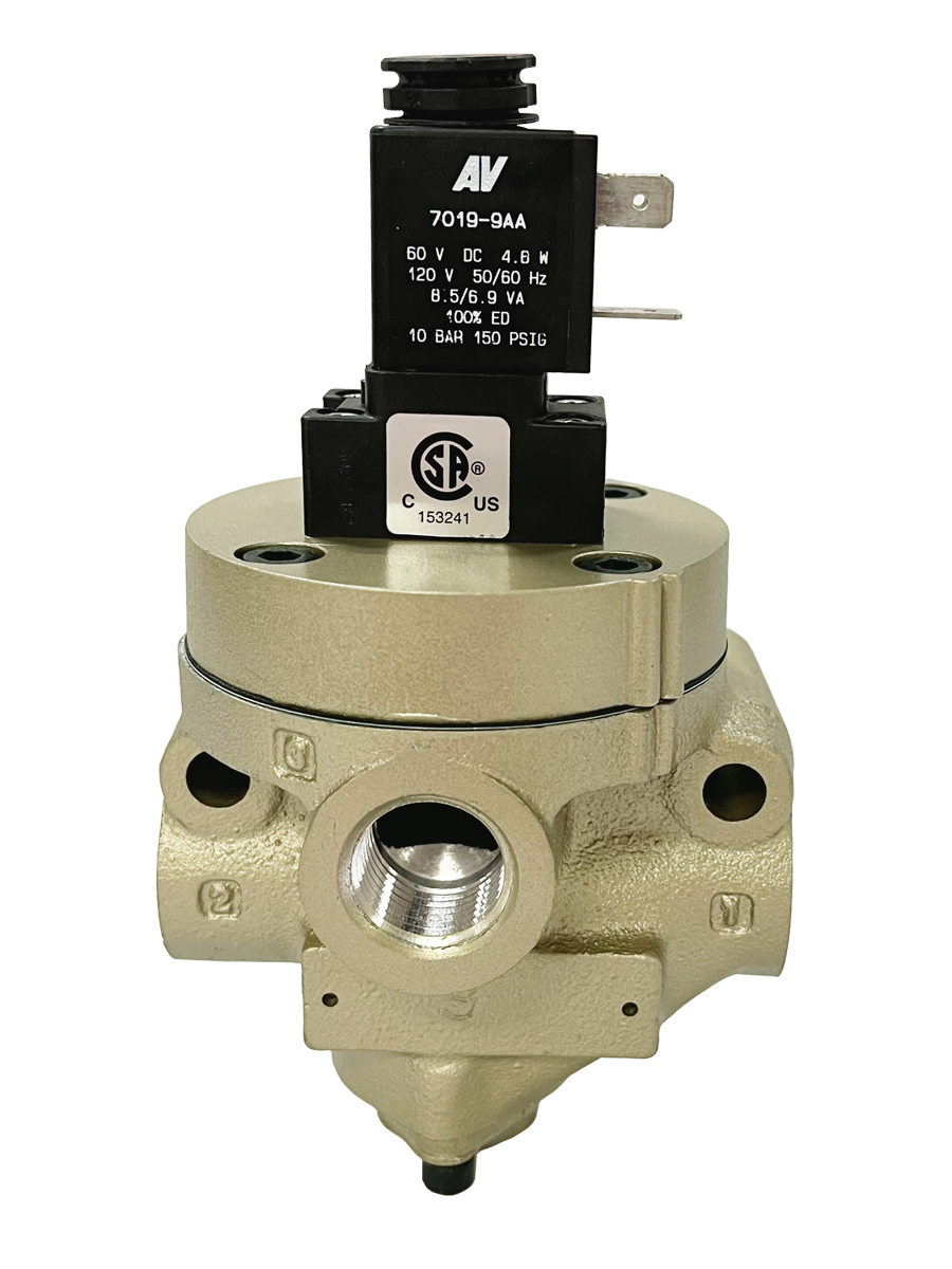
- For Standard, Low, and High Temperature Applications
- Port Sizes 1/4”- 1-1/2”
- High-flow and Positive Sealing
- Fast and Consistent Response Times
- No-stick Operation
- Self-cleaning and Strong Dirt Tolerance
- Long-life
- ROSS Replacement [https://www.rosscontrols.com/en/categories/131-inline-poppet-valves-21-27-series]
loading...
loading...
Product Overview
The Automatic Valve Pilot Poppet Valves series covers inline-mounted directional control valves for general automation, vacuum service, and hazardous location applications. Built on the proven inline poppet valve architecture, these valves deliver high flow capacity, positive sealing, and fast, consistent response times across a broad spectrum of industrial environments. Port sizes span 1/4" through 1-1/2" with matching flow coefficients from approximately 2.5 Cv to over 31 Cv depending on the configuration selected.
The poppet construction at the heart of this series provides fundamental performance advantages over spool-type valves. Perpendicular face seals create positive shutoff with no internal bypass leakage. High-velocity airflow across the poppet seats generates a self-cleaning action that removes particulate contamination during normal operation. The differential piston actuating mechanism produces overwhelming shifting forces that prevent sticking after extended idle periods or in contaminated air supply conditions.
Three application categories are covered in a single product family. General automation models operate in standard temperature environments from -18 C to 50 C ambient and 4 C to 80 C media. Vacuum service models are available for applications where inlet pressure drops below the minimum required for internally piloted operation, allowing external pilot supply with vacuum on the inlet. Hazardous location models carry the certifications required for Class I and Class II Division 1 environments, including explosion-proof solenoid pilot options conforming to NEMA 7 and ATEX standards. Low and high temperature variants extend the operating envelope to -40 C (-40 F) and 150 C (300 F) media respectively.
Key Engineering Features
- Perpendicular Poppet Face Seals - Face seals positioned at 90 degrees to the flow path create positive shutoff with near-zero leakage and no sliding action. This eliminates the seal wear mechanism inherent in spool valves and produces consistent sealing performance throughout service life.
- High-Flow Capacity with Positive Sealing - The poppet design delivers high flow paths while maintaining positive shutoff. Cv values range from approximately 2.5 to over 31 depending on port size and function, providing broad coverage for cylinder bore and speed requirements.
- Fast and Consistent Response Times - The differential piston design generates high actuating forces at all operating pressures, producing response times that remain consistent from the first cycle to millions of cycles. No break-in period is required.
- No-Stick Operation - Overwhelming shifting forces from the differential piston mechanism prevent valve elements from sticking after extended idle periods, contamination events, or thermal cycling. The valve responds reliably when called even after weeks of standby.
- Self-Cleaning and Strong Dirt Tolerance - High-velocity airflow is directed across the poppet seat interface during valve operation, providing a continuous self-cleaning action that expels particulate matter. This makes inline poppet valves significantly more tolerant of compressed air system contamination than spool designs.
- Standard, Low, and High Temperature Capability - Seal material options cover standard Buna-N for -18 to 50 C ambient, Buna-N for low temperature down to -40 C (-40 F), and Fluorocarbon for high temperature media up to 150 C (300 F) and ambient up to 122 C (250 F) on pressure-controlled versions.
- Vacuum Service Capability - Vacuum service models with external pilot supply allow the inlet port to be below atmospheric pressure while the valve is operated by an independent pilot circuit. Suitable for vacuum packaging, pick-and-place, and material handling systems.
- Hazardous Location Approvals - Explosion-proof solenoid pilot options are available for Class I Division 1 and Class II hazardous locations, covering NEMA 7 and ATEX classifications. These configurations are engineered for safe operation in environments where flammable gases or combustible dusts may be present.
- 2/2, 3/2, and 4/2 Valve Functions - 2/2 normally closed/open for on/off flow control, 3/2 normally closed/open for single-acting cylinder and signal switching, and 4/2 for double-acting cylinder control. All functions are available in solenoid pilot and pressure (air pilot) actuation.
- Internal or External Pilot Supply, Field-Convertible - Solenoid pilot models are configured for internal pilot supply as standard. Field conversion to external pilot supply is accomplished by relocating a pipe plug within the valve, without purchasing a different valve or returning to the factory.
- Non-Locking Manual Override Standard - Flush non-locking manual override buttons are standard on all single solenoid models. Double solenoid models include flush metal-button overrides. Manual overrides allow commissioning and troubleshooting without electrical power.
- Long Service Life with Self-Compensating Seals - The superior internal guidance system incorporates self-compensating seals that automatically adjust stroke as seals wear, maintaining sealing force without manual adjustment or periodic recalibration.
Technical Specifications
General Specifications
| Parameter | Specification |
| Valve Functions | 2/2 Normally Closed; 2/2 Normally Open; 3/2 Normally Closed; 3/2 Normally Open; 4/2 |
| Construction | Poppet (inline mounted) |
| Actuation | Solenoid Pilot (single and double); Pressure/Air Pilot |
| Port Sizes | 1/4", 3/8", 1/2", 3/4", 1", 1-1/4", 1-1/2" |
| Thread Types | NPT (standard); G / BSPP (with D prefix on model number) |
| Mounting | Inline; any orientation (vertical preferred for condensate drainage) |
| Operating Pressure (Standard) | 15 to 150 psig (1 to 10 bar) for 1/4" to 1-1/2" port sizes |
| Operating Pressure (Larger Port Sizes) | 30 to 150 psig (2 to 10 bar) for 1-1/2" to 2-1/2" port sizes |
| Maximum Flow (single solenoid pilot 3/2) | Up to 31 Cv at 1-1/4" to 1-1/2" port sizes |
| Flow Media | Filtered compressed air (5-micron filtration recommended) |
| Pilot Supply | Internal (standard); external (field-convertible or factory-ordered) |
| Manual Override | Non-locking button (single solenoid); flush metal button (double solenoid) |
| Seal Options | Buna-N (standard and low temperature); Fluorocarbon (high temperature) |
| Body Material | Cast aluminum |
| Poppet Material | Aluminum and stainless steel |
Temperature Ratings
Temperature ratings vary by actuation type and seal material. Standard solenoid pilot models use Buna-N seals. Low and high temperature configurations require specific seal and coil selection.
| Configuration | Ambient Temperature | Media Temperature |
| Standard Solenoid - Standard Temperature (Buna-N) | 4 to 50 C (40 to 122 F) | 4 to 80 C (40 to 175 F) |
| Solenoid - Low Temperature (Buna-N) | 40 to 50 C (-40 to 122 F) | 40 to 80 C (-40 to 175 F) |
| Solenoid - High Temperature (Fluorocarbon) | 17 to 82 C (0 to 180 F) | 17 to 150 C (0 to 300 F) |
| Pressure Controlled - Low Temperature (Buna-N) | 40 to 80 C (-40 to 175 F) | 40 to 80 C (-40 to 175 F) |
| Pressure Controlled - High Temperature (Fluorocarbon) | 17 to 150 C (0 to 300 F) | 17 to 150 C (0 to 300 F) |
Important: For media temperatures below 4 C (40 F), compressed air must be free of water vapor to prevent ice formation inside the valve. Low-temperature Buna-N seal models are available in 3/8" and 3/4" body sizes.
Electrical Data (Solenoid Pilot Valves)
Single solenoid pilot valves: 87 VA inrush, 30 VA holding (AC); 14 watts (DC). Double solenoid pilot valves: 190 VA inrush, 40 VA holding per solenoid (AC); 20 watts per solenoid (DC). All solenoids are continuous duty rated.
| Voltage | Power Consumption |
| AC (50/60 Hz) | 87 VA inrush / 30 VA holding (single solenoid); 190 VA inrush / 40 VA holding per solenoid (double) |
| DC (any) | 14 watts (single solenoid); 20 watts per solenoid (double solenoid) |
| Available voltages | AC and DC; contact Automatic Valve for specific voltage codes |
Electrical Connection Options
| Connection Type | Coil Code |
| Hardwired leads (standard) | standard |
| Explosion-proof conduit connection (NEMA 7) | hazardous location option |
| ATEX-rated coil option for Zone 1 and Zone 2 | ATEX option |
Flow Performance Data
Flow coefficients listed are average Cv for normally-closed 3/2 and 2/2 single solenoid pilot inline configurations. Values vary between NC and NO, and between inlet-to-outlet and outlet-to-exhaust paths. Consult the product catalog for full flow data tables.
| Port Size (In-Out) | Exhaust Port | Avg Cv NC (3/2) | Avg Cv NO (3/2) | Body Weight lb (kg) |
| 1/4" | 1/2" | 2.8 | 2.5 | 2.5 (1.1) |
| 3/8" | 1/2" | 4.0 | 3.0 | 2.5 (1.1) |
| 1/2" | 1" | 7.8 | 7.2 | included above |
| 3/4" | 1" | 9.4 | 7.2 | 3.3 (1.5) |
| 1" | 1-1/2" | 29 | 21 | included above |
| 1-1/4" | 1-1/2" | 31 | 22 | 7.0 (3.2) |
| 1-1/2" | 2-1/2" | 69 | 58 | 16.5 (7.4) |
Response Time Formula: Response Time (ms) = M + (F x V), where M is the minimum response constant (ms), F is the volume constant, and V is the downstream volume in cubic inches. M and F values are tabulated per port size, function (fill/exhaust), and valve series in the product catalog.
Certifications & Compliance
| Certification/Standard | Detail |
| Explosion-Proof Solenoid Pilot (Hazardous Location) | Explosion-proof coil options are available for Class I Division 1 hazardous location service. Consult Automatic Valve for specific certification markings, NEMA ratings, and approval documentation applicable to the configuration required. |
| ATEX Compliance | ATEX explosion-proof coil options are available for Zone 1 and Zone 2 hazardous area installations per European directive requirements. Consult Automatic Valve for ATEX certificate numbers and area classification details. |
| G (BSPP) Thread Option | G (ISO/BSPP) thread configurations are available by adding the D prefix to the model number, satisfying European and international piping standards without additional adapters. |
| CE Marking | Products conforming to EU Machinery Directive requirements carry CE marking. Consult Automatic Valve for Declaration of Conformity documentation. |
Typical Applications & Industries
General Automation and Machine Building
- Double-acting cylinder control using 4/2 inline poppet valves where high cycle durability, dirt tolerance, and consistent response times are required over the life of the machine without scheduled seal replacement.
- Single-acting spring-return cylinder and actuator control using 3/2 NC or 3/2 NO configurations for clamping, ejecting, and positioning functions on assembly and production equipment.
- Pneumatic logic and signal circuits where the poppet design's positive shutoff and near-zero leakage prevent circuit drift and signal corruption in sequenced multi-valve systems.
- High-flow exhaust circuits and quick-exhaust applications where the large-Cv poppet valves provide rapid cylinder retraction without restriction from undersized exhaust ports.
- Pilot signal supply for larger diaphragm or spool valves where a compact, fast inline poppet valve provides the actuating signal to a higher-flow main valve downstream.
Vacuum Material Handling and Packaging
- Vacuum cup suction and release control using external-pilot 2/2 NC poppet valves, where the poppet's positive sealing maintains vacuum on the cup without sustained solenoid energization.
- Vacuum pick-and-place systems for fragile components such as glass, ceramics, and thin-film products where the controlled on/off response of the poppet design prevents component damage from vacuum surge.
- Vacuum packaging lines using 3/2 poppet valves to switch between vacuum draw and purge air in flexible bag sealing and modified atmosphere packaging operations.
- Suction-cup conveyor systems on glass and sheet metal handling equipment where large Cv vacuum valves maintain required suction levels across multiple cups simultaneously.
High-Temperature and Low-Temperature Industrial Processes
- Steel mill and metals processing operations including hot rolling, annealing, and galvanizing lines where ambient temperatures exceed 120 F (50 C) and require high-temperature Fluorocarbon seal configurations rated to 300 F (150 C) media.
- Glass manufacturing facilities for directional air control of positioning cylinders and actuators operating adjacent to furnaces and forming stations at sustained high-temperature ambient conditions.
- Cold storage and refrigeration facility automation where low-temperature Buna-N seals maintain flexibility at -40 F (-40 C), ensuring cylinder actuation in deep-freeze zones.
- Arctic outdoor pipeline and processing installations requiring valve operation in ambient temperatures below -20 F (-29 C) without coil burnout or seal failure from cold-induced brittleness.
Hazardous Location and Petrochemical
- Oil and gas wellsite and production facility pneumatic equipment in Class I Division 1 flammable-atmosphere zones where explosion-proof solenoid coils are mandatory per NEC Article 500.
- Chemical plant reactors, storage vessels, and transfer pump stations where classified area pneumatic directional control valves must carry both explosion-proof electrical and corrosion-resistant body ratings.
- Grain handling and storage facilities in Class II Division 1 areas where combustible grain dust creates explosion hazard requiring explosion-proof or pressure-controlled (all-pneumatic) valve actuation.
- Paint and coating operations in Class I solvent atmosphere zones where pilot-operated poppet valves with explosion-proof coils provide reliable directional control without ignition risk.
Press, Stamping, and Power Equipment
- Pneumatic press clutch and brake control circuits where 2/2 and 3/2 inline poppet valves provide the fast response time and positive shutoff required for safe, precise press speed and stopping control.
- Stamping and blanking press air counterbalance systems using high-Cv 3/2 or 4/2 valves to rapidly charge and exhaust the large-volume counterbalance cylinders at each press stroke.
- Pneumatic power tool supply and shutoff valves in production lines where the high-velocity self-cleaning action of the poppet design tolerates the oil mist and contamination common in tool air supply systems.
- Safety air-dump circuits on large presses and forming machines where the poppet valve's positive shutoff guarantees rapid, complete venting of stored energy when the safety interlock is activated.
Food, Pharmaceutical, and Cleanroom Applications
- Food processing equipment requiring NEMA 4X or IP65 solenoid enclosures and corrosion-resistant materials for washdown environments where process hygiene is enforced.
- Pharmaceutical packaging and filling lines where the positive shutoff and zero-leakage characteristics of poppet valves prevent cross-contamination between process gas circuits.
- Cleanroom automation for semiconductor, medical device, and electronics manufacturing where the poppet's self-cleaning mechanism reduces particle shedding compared to spool designs with close-clearance sliding parts.
- Outdoor and exposed-environment food and beverage processing where the standard solenoid enclosure ratings protect against ambient weather conditions without additional weatherproof housings.
Ordering and Model Number Configuration
Pilot Poppet Valves are ordered using the valve function, port size, actuation type, voltage, seal material, and temperature range. Standard NPT models are ordered directly; G (BSPP) thread models use the D prefix. Low-temperature and high-temperature configurations require specific seal and coil code selection. External pilot supply configurations are available factory-ordered or field-convertible from standard internal pilot models.
|
Pilot Poppet Valve Model Number Structure (Single Solenoid 3/2 Example):
277 3 B 200 1 W - 1 | | | | | | | 277 = Series (21 Series = 21x; 27 Series = 27x) | 3 = Actuation (3 = Single Solenoid; 6 = Double Solenoid; 5 = Pressure/Air Pilot) | B = Function (1 = 2/2 NC; 2 = 2/2 NO; 3 = 3/2 NC; 4 = 3/2 NO; 6 = 4/2) | 200 = Body/Port Size Code (200=1/4"; 300=3/8"; 400=1/2"; 500=3/4"; 600=1"; 700=1-1/4"; 800=1-1/2") | 1 = Seal Material (1 = Fluorocarbon/high temp; 2 = Buna-N standard; low-temp available) | W = Voltage Code (H = 12 VDC; W = 24 VDC; Z = 120 VAC/60 Hz; Y = 240 VAC/60 Hz) | 1 = Coil Type (1 = DIN Form A; 2 = DIN Form B; 3 = M12; 4 = 1/2" Conduit standard; 5 = DIN Form B low temp; 6 = 1/2" Conduit high temp)
For G (BSPP) thread: add D prefix to the model number. Example: 2773B2001 = 27 Series, single solenoid 3/2 NC, 1/4" port, NPT Example: 2774B2001 = 27 Series, single solenoid 3/2 NO, 1/4" port, NPT Example: 2776B2001 = 27 Series, double solenoid 4/2, 1/4" port, NPT |
Port sizes are encoded in the body/port size code position: 200 = 1/4", 300 = 3/8", 400 = 1/2" or 1/2"-1", 500 = 3/4"-1", 600 = 1"-1-1/2", 700 = 1-1/4"-1-1/2", 800 = 1-1/2"-2-1/2".
Voltage codes: H = 12 VDC; W = 24 VDC; Z = 120 VAC 60 Hz; Y = 240 VAC 60 Hz.
Seal material code 1 = Fluorocarbon (high temperature, media to 300 F / 150 C); code 2 = Buna-N (standard). Low-temperature Buna-N configurations available in 3/8" and 3/4" body sizes.
For G (BSPP) thread configurations, add D as a prefix to the model number (e.g., D2773B2001).
External pilot supply configuration: field-convertible from internal pilot by relocating the pipe plug between the external pilot port and the internal pilot passage. Factory-ordered external pilot models are also available.
3/2 Single Solenoid Pilot Inline Valve - Normally Closed and Normally Open (27 Series Reference)
| Port Size In-Out | Model NC | Model NO | Avg Cv NC | Avg Cv NO | Weight lb (kg) |
| 1/4" - 1/2" | 2773B2001 | 2774B2001 | 2.8 | 2.5 | 2.5 (1.1) |
| 3/8" - 1/2" | 2773B3001 | 2774B3001 | 4.0 | 3.0 | 2.5 (1.1) |
| 1/2" - 1" | 2773B4001 | 2774B4001 | 7.8 | 7.2 | included above |
| 3/4" - 1" | 2773B5001 | 2774B5001 | 9.4 | 7.2 | 3.3 (1.5) |
| 1" - 1-1/2" | 2773B6001 | 2774B6001 | 29 | 21 | 3.3 (1.5) |
| 1-1/4" - 1-1/2" | 2773B7001 | 2774B7001 | 31 | 22 | 7.0 (3.2) |
4/2 Double Solenoid Pilot Inline Valve (27 Series Reference)
| Port Size In-Out | Model | Avg Cv | Weight lb (kg) |
| 1/4" - 1/2" | 2776B2001 | 2.5 | 3.0 (1.4) |
| 3/8" - 1/2" | 2776B3001 | 3.6 | 3.0 (1.4) |
| 1/2" - 1" | 2776B4001 | 6.9 | 3.0 (1.4) |
| 3/4" - 1" | 2776B5001 | 8.2 | 5.3 (2.4) |
| 1" - 1-1/2" | 2776B6001 | 23 | 5.3 (2.4) |
| 1-1/4" - 1-1/2" | 2776B7001 | 24 | 11.3 (5.1) |
Accessories
Exhaust Silencers
Aluminum exhaust silencers are available for port sizes 1/2", 1", and 1-1/2" to reduce exhaust noise to acceptable industrial levels. Silencers thread directly into exhaust ports and must have flow capacities at least equal to the exhaust Cv of the valve to prevent back pressure.
Warning: Contaminated or flow-restricted silencers increase exhaust back pressure and can cause incomplete valve shifting or erratic response. Inspect and replace silencers at regular intervals on high-cycle applications.
Manual Override Kits
Flush button (locking and non-locking) and extended button manual override kits are available for single and double solenoid models. Locking overrides can be held in the actuated position using a screwdriver for extended maintenance periods. Non-locking overrides are spring-returned.
Indicator Light Kit
An indicator light extends through the solenoid or pilot cover and illuminates when the solenoid is energized, providing visual status indication for troubleshooting and commissioning. Available for single solenoid models. Standard on double solenoid models.
LOGICAIR Adaptors
Specialty pneumatic logic adaptors are available for the inline poppet valve platform: Timed Sequence Adaptor for delays up to 30 seconds (2/2) or 3 seconds (3/2 and 4/2); PB Adaptor for low pilot pressure service; Air Index Adaptor for impulse-controlled detented operation from a single momentary signal; Q Adaptor for extended time delays to 60 seconds.
Related Products & Accessories
- Direct Acting Solenoid Valves (K02 Series) - Compact direct-acting poppet solenoid valves for 2/2 and 3/2 functions at 1/8" and 1/4" ports, vacuum to 150 psig. https://www.automaticvalve.com/series/218-direct-acting-solenoid-valves
- ISO 5599-1 Valves (I15, I20, I45 Series) - ISO 5599/1 conforming base-mount spool valves for 5/2 and 5/3 functions with SIL certification. https://www.automaticvalve.com/series/229-iso-5599-1-valves
- SAE Valves (A04, A06, A20 Series) - SAE J2051 conforming high-flow spool valves from 2.4 to 22.7 Cv for automotive and heavy industrial applications. https://www.automaticvalve.com/series/228-sae-valves
- ROSS Controls Inline Poppet Valves 21 and 27 Series - Complete inline poppet valve catalog from ROSS Controls, the parent company, covering standard, vacuum, low temperature, and high temperature configurations. https://www.rosscontrols.com/en/categories/131-inline-poppet-valves-21-27-series
Frequently Asked Questions (FAQ)
Q: What makes poppet valve construction superior to spool valves for contaminated air applications?
A: Poppet valves use face seals rather than close-clearance sliding fits. The smallest cross-section in the flow path is at the poppet seat, where air velocity is highest. This high-velocity air continuously removes particulate contamination from the seat area during valve operation. Spool valves rely on tight clearances that trap particles and cause binding. For compressed air systems with below-average filtration or contamination ingress, poppet valves deliver significantly longer service intervals.
Q: What is the difference between standard, low-temperature, and high-temperature configurations?
A: Standard configurations use Buna-N seals and hardwired solenoids rated for 4 to 50 C ambient and 4 to 80 C media. Low-temperature configurations use Buna-N seals with low-temperature coils rated to -40 C ambient and media. High-temperature configurations use Fluorocarbon seals rated to 150 C media and, for pressure-controlled (non-solenoid) versions, up to 150 C ambient. Choose the configuration based on where the valve is physically installed and the temperature of the compressed air supply.
Q: How do I convert an internally-piloted valve to external pilot supply in the field?
A: On internally-piloted inline poppet valves, removing the pilot section, relocating the pipe plug from the external pilot port to the internal pilot passage, and replacing the pilot section completes the conversion. No special tools or parts are required beyond a replacement pipe plug. After conversion, connect a 1/8" pilot supply line to the external pilot port at a pressure equal to or greater than the main inlet pressure.
Q: What is the minimum pilot pressure required for external pilot operation?
A: For external pilot supply, pilot pressure must be equal to or greater than the inlet pressure and must also meet the minimum 30 psig operating pressure threshold. Do not use an external pilot at a pressure lower than the main inlet pressure, as this can result in incomplete valve shifting.
Q: Are vacuum service configurations available, and how do they differ from standard models?
A: Vacuum service models use external pilot supply, which allows the inlet port to operate at sub-atmospheric (vacuum) pressure while the pilot circuit operates at positive pressure (minimum 30 psig). Standard internally-piloted models require a minimum 15 to 30 psig inlet pressure for pilot actuation. For vacuum pick-and-place or vacuum packaging applications, specify the external pilot configuration.
Q: What certifications are required for Class I Division 1 hazardous locations?
A: For Class I Division 1 installations (flammable gas or vapor), the solenoid enclosure must carry FM and/or CSA explosion-proof approval and be rated NEMA 7 (and Class II NEMA 9 for dust). The coil must be installed in the approved enclosure with sealed conduit entries per NEC Article 500. Automatic Valve offers explosion-proof coil options for hazardous location inline poppet valve configurations.
Q: What response time can I expect from inline poppet valves?
A: Response time follows the formula: Time (ms) = M + (F x V), where M is the minimum shift time constant for the valve, F is the volume-dependent constant, and V is the downstream volume in cubic inches. M values for 1/4" port valves are approximately 10 ms. Larger port sizes have proportionally higher M constants. Actual system response depends on downstream volume, pressure, and flow restrictions. Consult the catalog for specific M and F values by port size and function.
Q: Do I need to lubricate inline poppet valves?
A: Lubrication is not required. The poppet design operates reliably on clean, dry compressed air throughout its service life. If lubrication is added to the compressed air supply for other components in the system, use petroleum-based lubricants with an aniline point between 82 C and 99 C (180 F to 210 F) at approximately one drop per minute. Avoid phosphate-ester and synthetic lubricants that cause Buna-N seal swelling.
Q: What seal material should I specify for high-temperature applications?
A: Specify Fluorocarbon (FKM/Viton) seals for media temperatures above 80 C (175 F) and up to 150 C (300 F). For solenoid pilot models, the ambient temperature limit with Fluorocarbon seals is 82 C (180 F). For ambient temperatures above 82 C, specify pressure-controlled (air pilot) actuation with Fluorocarbon seals, which extends the ambient limit to 150 C (300 F) for media-only and ambient temperature both.
Q: Can inline poppet valves be used in any mounting orientation?
A: Yes. Inline poppet valves can be mounted in any orientation. Vertical mounting with the solenoid facing upward is preferred because it promotes condensate drainage away from the solenoid coil and allows gravity-assisted poppet return. Avoid mounting with the solenoid facing straight down, which can trap condensate at the coil.
Q: What is the maximum operating pressure for inline poppet valves?
A: Maximum operating pressure is 150 psig (10 bar) for all port sizes from 1/4" to 2-1/2". The minimum pressure varies: 15 psig for 1/4" to 1-1/2" port sizes using internal pilot, and 30 psig for 1-1/2" to 2-1/2" port sizes. External pilot configurations allow lower inlet pressures down to vacuum.
Q: What is the lead time for pilot poppet valves?
A: Standard manufacturing lead times for quantities of 10 or fewer units are approximately 3 to 4 weeks with shipping available throughout the United States. Contact Automatic Valve at (248) 474-6761 for volume pricing, special configurations, and expedited delivery options.
Installation & Maintenance Guidelines
- Mount valves in any orientation; vertical installation with solenoid up is preferred to encourage condensate drainage and optimal pilot operation.
- Supply filtered air at 5-micron filtration minimum to maximize valve life and prevent contamination of poppet seats. Dirt tolerance is high but clean air extends service intervals significantly.
- Ensure supply line sizes are adequate and free of crimps, sharp bends, or partially closed valves that could restrict supply flow below the minimum pressure threshold.
- For solenoid pilot controlled models: inlet pressure must be 15 psig minimum (1/4" to 1-1/2" ports) or 30 psig (1-1/2" to 2-1/2" ports). Pressures below these thresholds result in incomplete valve shifting.
- For external pilot supply models: pilot pressure must equal or exceed inlet pressure and meet the minimum pilot pressure requirement of 30 psig. Never supply pilot at less than inlet pressure.
- For high-temperature installations above 82 C ambient with solenoid models: verify that the solenoid coil is rated for the application temperature and that Fluorocarbon seals are specified. Solenoid ambient limit is 82 C maximum.
- For low-temperature installations below 4 C: specify low-temperature Buna-N seals and supply air dried to a dew point below the minimum ambient operating temperature to prevent ice formation inside the valve.
- Do not restrict exhaust ports or piped exhaust lines. Exhaust back pressure reduces valve shifting speed and can prevent complete cycling. Size exhaust silencers to have Cv equal to or greater than the valve's exhaust Cv.
- Perform manual override testing during commissioning to verify pneumatic circuit function before energizing solenoids. This confirms proper supply, actuator connections, and cylinder function independently of electrical systems.
- Pilot section maintenance: recondition kits are available for single and double solenoid pilots. Order by kit number based on temperature service (high or low) and solenoid type. Order replacement solenoids by part number specifying voltage and hertz.
Warranty & Global Support
Automatic Valve, a member of the ROSS Controls global family, provides technical support for pilot poppet valve selection, hazardous location compliance, and system troubleshooting.
For explosion-proof approval documentation, ATEX certificates, and application guidance for hazardous location installations, contact Automatic Valve at (248) 474-6761 or visit automaticvalve.com.
ROSS Controls global support is available through offices in the USA, Canada, Brazil, Germany, France, United Kingdom, India, China, and Japan, providing local technical resources for international machine builders and OEMs.
Product catalogs, installation instructions, and maintenance documentation are available for download at automaticvalve.com.
Download Catalog: https://www.automaticvalve.com/documents/406/Directional_Control_Poppet_Valves_Valves_Service_Form__AV-DCPV-OI.pdf
Download Documents
Pilot Poppet Valves