



SAE Valves A04, A06, A20 Series
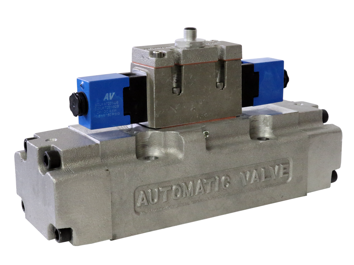
 Product Catalog - SAE Valves
 Explosion-Proof
Product Catalog - SAE Valves
Product Catalog - SAE Valves Explosion-Proof
- Conforms to SAE J2051 specifications for series 125, 250 and 1000
- Flow Range of 2 to 20 Cv
- Complete range of bases and operators available
- Additional models available, please view downloadable literature
loading...
loading...
Product Overview
The Automatic Valve A04, A06, and A20 Series are SAE J2051-conforming directional control valves covering SAE interface series 125 (A04), 250 (A06), and 1000 (A20). Built for the demanding flow and reliability requirements of automotive production equipment, press lines, heavy machinery, and large-format automation, these spool valves deliver flow coefficients from 2.4 Cv to 22.7 Cv with matching sub-base, manifold, and mounting hardware options.
All three series are available in 5/2 (4-way 2-position) and 5/3 (4-way 3-position) configurations with single spring-return, double detented, and spring-centered functions. Operators include solenoid pilot (single and double), air pilot, and hand lever. A complete range of body type options covers valve-only (407), valve with sub-base (409), valve with manifold base with bottom cylinder ports (413), and valve with manifold base with bottom/side cylinder ports (416), ensuring a proper mounting solution for any installation configuration.
Solenoid coil options range from standard weather-proof DIN 43650 to explosion-proof CSA/FM and ATEX coils for hazardous location compliance. The A04 and A06 Series also offer automotive OEM electrical connection options including GM, Ford, and Chrysler mini and micro connector standards for direct integration into vehicle and automated assembly equipment. The combination of SAE J2051 interchangeability, high flow capacity, and broad certification coverage makes the A Series the standard choice for large pneumatic automation systems in automotive and industrial manufacturing.
Key Engineering Features
- SAE J2051 Conformance (Series 125, 250, and 1000) - Valve bodies conform to SAE J2051 interface specifications, ensuring physical interchangeability with any SAE-rated sub-base or manifold. This protects capital investment in existing base infrastructure when valves are upgraded or replaced.
- High-Flow Capacity Across Three Sizes - A04 delivers 2.4 Cv (2,360 l/min); A06 delivers 8.6 Cv (8,460 l/min); A20 delivers 22.7 Cv (22,340 l/min) in the 5/2 function. This flow range covers small to very large actuators in a single product family.
- 5/2 and 5/3 Functions Available - Single spring-return, double detented, and 5/3 three-position (block, exhaust, and pressure center) configurations cover the full range of cylinder control requirements from simple extend/retract to mid-stroke hold and floating center.
- Complete Range of Body and Mounting Types - Valve-only (407), valve with sub-base (409), valve with bottom-port manifold (413), and valve with bottom/side-port manifold (416) provide a matched mounting solution for any panel, machine, or field installation.
- Automotive OEM Connector Options - Available with Ford 5-pin mini (Option 4), GM 5-pin micro (Option 5), Chrysler 4-pin mini (Option 6), and other automotive OEM electrical connectors for direct integration into automotive assembly and test equipment.
- Weather-Proof and Explosion-Proof Coil Options - Standard weather-proof NEMA 4X coils, CSA/FM explosion-proof coils (Class I Division 1 Groups A-D), and ATEX explosion-proof coils extend the A Series to hazardous area installations without custom engineering.
- Fluoroelastomer Seal Option - Option A specifies fluoroelastomer (FPM/FKM) seals in place of standard Buna-N, extending chemical resistance and providing an upgrade path for applications with petroleum, oil, or chemical mist exposure.
- Internal or External Pilot Supply - Internal pilot operates when inlet pressure is 35 to 150 psig. External Pilot Option B provides a separate pilot port for circuits where inlet pressure drops below 35 psig or vacuum is applied to the inlet.
- Solenoid and Air Pilot Operators - Solenoid pilot (single and double) and air pilot operators are available for all three series. Hand lever operators (A04 and A06) allow manual override and lockout for maintenance procedures.
- Broad Voltage Compatibility - Coils available in 12 VDC, 24 VDC, 110/120 VAC, 220/240 VAC, and 125 VDC to match North American, European, and export machine voltage standards across all three series.
Technical Specifications
General Specifications
| Parameter | Specification |
| Valve Series | A04 (SAE J2051 Series 125), A06 (SAE J2051 Series 250), A20 (SAE J2051 Series 1000) |
| Standard | SAE J2051 Series 125, 250, and 1000 |
| Valve Functions | 5/2 Single (NC, spring return); 5/2 Double (detented); 5/3 Block Center; 5/3 Exhaust Center; 5/3 Pressure Center |
| Construction | Spool |
| Actuation | Solenoid Pilot (single and double); Air Pilot (single and double); Hand Lever (A04 and A06) |
| Operating Pressure (2-Position) | 35 to 150 psig (240 to 1030 kPa) |
| Operating Pressure (3-Position) | 50 to 150 psig (345 to 1030 kPa) |
| External Pilot Option B Range | Vacuum to 35 psig inlet; 35 to 150 psig external pilot |
| Flow Media | Air or inert gas; lubrication not required but recommended; if used, specify medium aniline point petroleum-based lubricant |
| Manual Override | Push non-locking (standard on solenoid models) |
| Seal Material | Treated Buna-N (NBR, standard); Fluoroelastomer FPM/FKM (Option A) |
| Valve Body Material | Aluminum |
| Ambient Temperature | 18 to 50 C (0 to 123 F) |
| Media Temperature | 18 to 50 C (0 to 123 F) |
Temperature Ratings
Temperature ratings apply to both ambient and media conditions. All standard models operate at -18 to 50 C (0 to 123 F). High-temperature coil Option CT extends ambient limit to 82 C (180 F).
| Configuration | Ambient Temperature | Media Temperature |
| Standard Buna-N or FPM seals (all functions) | 18 to 50 C (0 to 123 F) | 18 to 50 C (0 to 123 F) |
| High Temp Coil Option CT | 18 to 82 C (0 to 180 F) | 18 to 82 C (0 to 180 F) |
Important: For media temperatures below 4 C (40 F), compressed air must be free of water vapor to prevent ice formation inside the valve.
Electrical Data (Solenoid Pilot Valves)
All solenoid coils are rated for 100% continuous duty. Power values are nominal at rated voltage; voltage tolerance is +/-10% of nominal. S = standard coil; Y = explosion-proof coil.
| Voltage | Power Consumption |
| 12 VDC (-DA) | 4.4 W (standard) / 4.5 W (explosion-proof) |
| 24 VDC (-DB) | 4.4 W (standard) / 4.5 W (explosion-proof) |
| 110/120 VAC 50/60 Hz (-AA) | 6.9 VA (standard) / 6.5 VA (explosion-proof) |
| 220/240 VAC 50/60 Hz (-AB) | 6.9 VA (standard) / 6.8 VA (explosion-proof) |
| 125 VDC (-DE, Y coil only) | 5.5 W |
Electrical Connection Options
| Connection Type | Coil Code |
| DIN 43650 Form B (standard weather-proof, NEMA 4X) | Standard (S) |
| 1/2" Conduit with 24" Leads (Explosion-Proof, CSA/FM, NEMA 4/4X/7C/7D/9) | Y |
| ATEX Explosion-Proof (Zone 1) | consult factory |
| Ford 5-Pin Mini Connector | Option 4 |
| GM 5-Pin Micro Connector | Option 5 |
| Chrysler 4-Pin Mini Connector | Option 6 |
| Additional OEM Automotive Connectors | Options 0-7 (consult catalog) |
Flow Performance Data
Flow performance data for A Series valves at standard operating pressure of 35 to 150 psig. A20 (1000 Series) Cv exceeds the formal 2 to 20 Cv range stated for the A04/A06 due to the large-bore Series 1000 interface.
| Series | SAE J2051 | 5/2 Cv | 5/2 Flow (l/min) | 5/3 Cv | 5/3 Flow (l/min) | Body Weight kg (lb) |
| A04 | Series 125 | 2.4 | 2360 | 1.9 | 1841 | 3.7 (8.3) |
| A06 | Series 250 | 8.6 | 8460 | 6.7 | 6599 | consult catalog |
| A20 | Series 1000 | 22.7 | 22340 | 17.7 | 17425 | 8.7 (19.4) |
Certifications & Compliance
| Certification/Standard | Detail |
| SAE J2051 Conformance | Valve bodies conform to SAE J2051 interface specifications for Series 125 (A04), 250 (A06), and 1000 (A20), providing physical and dimensional interchangeability with any SAE J2051 sub-base or manifold. |
| CSA Approval (Explosion-Proof) | Explosion-proof coil Option Y is CSA approved (C22.2 and UL STD 429) for Class I Division 1 Groups A, B, C, D; Class II Groups E, F, G; Class III; T4; Ta = -20 to +60 C; NEMA 4, 4X, 7C, 7D, 9. |
| Factory Mutual (FM) Approval | Factory Mutual approved for explosion-proof installations in Class I Division 1 hazardous locations with Option Y explosion-proof coil. |
| ATEX Compliance | ATEX explosion-proof coil option available for Zone 1 and Zone 2 hazardous areas. Consult Automatic Valve for ATEX documentation and area classification requirements. |
| CE Marking | Products meet CE requirements for EMF and Low Voltage Directives for industrial use in the European Union. |
Typical Applications & Industries
Automotive Body Shop and Stamping
- Spot weld gun opening and closing circuits on automotive body assembly lines using A06 or A20 valves to provide the high Cv needed for rapid large-bore cylinder response at production speeds.
- Transfer press automation including die clamping, blank feeder actuation, and part ejector systems where A20 Series valves deliver up to 22.7 Cv to drive cylinders with bore diameters of 4 inches and above.
- Hemming and roller forming press hydraulic-pneumatic hybrid circuits where SAE J2051 valve interchangeability protects existing base plate investments across multi-press production lines.
- Robot end effector and tool changer pneumatic supplies using double 5/2 detented A04 valves to maintain clamp position with no solenoid energization during the weld or assembly dwell.
Automotive Final Assembly and Test
- Assembly line fixture clamping and positioning systems where automotive OEM connector options (Ford, GM, Chrysler 4- and 5-pin) integrate directly into vehicle harness test connectors without adapter wiring.
- Vehicle end-of-line test equipment requiring precisely controlled pneumatic actuators and consistent switching performance to achieve repeatable test cycle times.
- Tire and wheel assembly machines using A20 Series valves to control the large-bore cylinders required for bead seating and inflation operations.
- Door, hood, and liftgate assembly fixtures using A04 or A06 Series with 5/3 block-center configurations to hold panel position during adhesive cure or spot weld operations.
Industrial Presses and Forming Equipment
- Hydraulic press cushion and counterbalance circuits using A20 Series high-flow valves to manage large-volume air chambers at the response speeds demanded by press cycle rates.
- Metal forming and coining press actuation where A06 valves at 8.6 Cv provide the flow capacity needed to drive double-acting press cylinders at 60 to 100 strokes per minute.
- Forging and hot-forming operations where standard temperature performance (-18 to 50 C) is adequate for the valve itself, with the high-flow A20 valve matching large bore actuator requirements.
- Blanking and punching press flywheel clutch and brake actuators that require extremely fast response from large-volume air circuits to meet safety system demands.
Defense and Heavy Industrial Equipment
- Military vehicle and ground support equipment pneumatic systems where SAE J2051 standardization aligns with DoD component standardization requirements for interchangeable spare parts.
- Mining and mineral processing equipment using A20 Series valves in large-bore cylinder circuits for conveyor gates, dump body actuation, and material transfer equipment.
- Construction equipment pneumatic control systems including chassis leveling, tire inflation, and tool actuation circuits that benefit from the A20's 22.7 Cv capacity.
- Marine and offshore platform equipment where explosion-proof CSA/FM approval and stainless steel accessory options extend the A Series to classified deck environments.
General High-Flow Automation
- Large-format packaging machinery including case erectors, pallet wrapping systems, and stretch hooding equipment where actuator bore sizes exceed the flow capacity of ISO 5599/1 standard valves.
- Tire building and retreading equipment using A20 Series valves for green tire press actuation and bladder inflation circuits requiring high flow at precise pressure control.
- Foundry and sand casting equipment using A06 or A20 valves for core box actuation and sand injection circuits in moderate-temperature industrial environments.
- Hydraulic-pneumatic hybrid test stands and proof-test equipment where the SAE J2051 interface and high Cv allow precise simulation of large actuator loading conditions.
Hazardous Location Industrial Processing
- Petrochemical and refinery processing facilities requiring CSA/FM explosion-proof solenoid valves on compressed air-operated equipment in Class I Division 1 classified areas.
- Chemical processing plants with ATEX Zone 1 area classifications requiring explosion-proof pneumatic directional valves for large-bore actuator control.
- Grain storage and flour milling facilities in Class II Group G environments where explosion-proof coil approval prevents ignition of combustible dust atmospheres.
- Paint finishing and solvent coating operations in Class I classified areas where the A04 or A06 Series with explosion-proof coils meet the electrical equipment requirements of NFPA 33.
Ordering and Model Number Configuration
The A Series model number identifies the body type prefix (407/409/413/416), valve series (A04/A06/A20), port location, port size, function, operator, and voltage. Options are appended as suffixes. Electrical connector options are specified as numeric suffixes after the voltage code.
|
SAE Valve Model Number Structure:
407 / 409 / 413 / 416 - Body Type | 407 = Valve Only | 409 = Valve + Sub-Base | 413 = Valve + Manifold (Bottom Cylinder Ports) | 416 = Valve + Manifold (Bottom/Side Cylinder Ports) | B - Series (A04=43, A06=67, A20=12) | 43 - Port Size Code (43=3/8"; 67=3/4"; 12=1-1/4"; 65=1/2"; 60=1") | S - Operator 1 (S = Weather-Proof Solenoid; 1A = Air Pilot; 3B = Hand Lever) | 39 - Function Code (39 = 5/2 Single NC; S3 = 5/3 Block; DS3 = 5/3 Exhaust; 1A = 5/3 Pressure; 7A = 5/2 Detent) | A - Operator 2 (A = Spring Return; S3 = 3-pos spring center; DS3 = detent) | AA - Voltage Code (-AA = 110/120 VAC; -AB = 220/240 VAC; -DA = 12 VDC; -DB = 24 VDC) | (Y) - Option Y = Explosion-Proof Coil CSA/FM; A = Fluoroelastomer seals
Example: 407B43S39A-AA = Valve Only, A04 (125 Series), 3/8" port, single solenoid 5/2 NC, spring return, 120 VAC Example: 407B12S39A-AAY = Valve Only, A20 (1000 Series), 1-1/4" port, single solenoid 5/2 NC, spring return, 120 VAC, Explosion-Proof Example: 409B43S39A-DB = Valve + Sub-Base, A04, 3/8" sub-base port, 5/2 NC, 24 VDC |
Voltage codes: -AA = 110/50 or 120/60 Hz; -AB = 220/50 or 240/60 Hz; -DA = 12 VDC; -DB = 24 VDC; -DE = 125 VDC (explosion-proof Y coil only).
Options appended after voltage code: A = Fluoroelastomer seals; B = External pilot supply; D = Dustproof; Y = Explosion-Proof coil CSA/FM (NEMA 4/4X/7C/7D/9). Automotive OEM connector options: 4 = Ford 5-pin mini; 5 = GM 5-pin micro; 6 = Chrysler 4-pin mini; additional options 0-7 available.
Port size codes on sub-bases and manifolds: 42 = 1/4"; 43 = 3/8"; 65 = 1/2"; 67 = 3/4"; 60 = 1"; 12 = 1-1/4"; 15 = 1-1/2".
Not all options are available for all models and series combinations. Contact Automatic Valve at (248) 474-6761 for option availability and custom configurations.
A Series Flow Capacity and SAE J2051 Reference
| Series | SAE J2051 Series | 5/2 Cv | 5/3 Cv | Base Sub-Base Port Size (409) | Manifold Port Size (416) |
| A04 | 125 | 2.4 | 1.9 | 1/4" | 3/8" |
| A06 | 250 | 8.6 | 6.7 | 1/2", 3/4", 1" | 1/2", 3/4" |
| A20 | 1000 | 22.7 | 17.7 | 1-1/4", 1-1/2" | n/a |
Accessories
Sub-Bases (409 Prefix)
Individual sub-bases mount a single A Series valve and provide external NPT port connections in the required pipe sizes. Sub-base models are ordered using the 409 body type prefix with the appropriate port size code. Sub-bases are rated to 150 psig and sized to match the valve series.
Manifold Bases with Bottom Cylinder Ports (413 Prefix)
Multi-station manifold bases with bottom-exit cylinder ports allow bottom panel mounting with pipe connections routed downward. Available for A04 (125 Series) and A06 (250 Series). Common supply and exhaust galleries simplify piping.
Manifold Bases with Bottom/Side Cylinder Ports (416 Prefix)
Multi-station manifold bases with cylinder ports accessible from both the bottom and side panels provide flexible routing for piping constrained installations. Available for A04 and A06 Series. Models include 3/8" (A04) and 1/2" to 3/4" (A06) cylinder port options.
Related Products & Accessories
- ISO 5599-1 Valves (I15, I20, I45 Series) - ISO 5599/1 conforming spool valves for Size 1, 2, and 3 applications where ISO interface standardization is required instead of SAE. https://www.automaticvalve.com/series/229-iso-5599-1-valves
- Direct Acting Solenoid Valves (K02 Series) - Compact direct-acting poppet solenoid valves for small-bore circuits requiring 2/2 and 3/2 functions at vacuum to 150 psig. https://www.automaticvalve.com/series/218-direct-acting-solenoid-valves
- Pilot Poppet Valves (General, Vacuum, Hazardous) - Inline pilot poppet valves for standard, low, and high temperature applications with port sizes 1/4" to 1-1/2". https://www.automaticvalve.com/series/2762-pilot-poppet-valves
Frequently Asked Questions (FAQ)
Q: What does SAE J2051 conformance mean and why does it matter?
A: SAE J2051 is the Society of Automotive Engineers standard that defines physical interface dimensions, port locations, and mounting hole patterns for pneumatic directional control valves. Conformance means A Series valve bodies can be mounted on any SAE J2051-rated sub-base or manifold from any manufacturer. This protects existing machine designs from a single-supplier dependency and simplifies spare parts management across a fleet of similar machines.
Q: How do I select between A04, A06, and A20 Series?
A: Select based on the required flow coefficient and the SAE interface size already installed on the equipment. A04 (2.4 Cv) is appropriate for small to medium bore cylinders. A06 (8.6 Cv) handles medium to large bore applications. A20 (22.7 Cv) is required for very large bore cylinders, typically 4 inches and above, or applications demanding fast fill times. Match the series to the sub-base port size already on the equipment.
Q: What is the maximum flow capacity of the A20 Series?
A: The A20 Series (SAE J2051 Series 1000) delivers 22.7 Cv (22,340 l/min) in the 5/2 function and 17.7 Cv (17,425 l/min) in the 5/3 function. This is among the highest flow capacities available in a base-mount solenoid directional control valve and is sized for the largest pneumatic cylinders in automotive stamping, press, and heavy industrial applications.
Q: Are automotive OEM electrical connectors available for A Series valves?
A: Yes. The A04 and A06 Series offer automotive OEM connector options including Ford 5-pin mini (Option 4), GM 5-pin micro (Option 5), and Chrysler 4-pin mini (Option 6). Additional connector options numbered 0 through 7 are available. These allow direct connection to automotive assembly and test harnesses without adapter wiring.
Q: What body type should I specify for my installation?
A: Valve-only (407 prefix) requires a separately ordered sub-base and is used when an existing sub-base is already installed. Valve with sub-base (409 prefix) is a complete unit ready for pipe connection. Valve with manifold base (413 or 416 prefix) integrates multiple valves on a common assembly with shared supply and exhaust. Choose based on whether single or multi-valve mounting is required and the available panel space.
Q: What is the minimum supply pressure for A Series valves?
A: For 5/2 (two-position) functions, minimum supply pressure is 35 psig (240 kPa) using internal pilot. For 5/3 (three-position) spring-centered functions, minimum pressure is 50 psig (345 kPa) to achieve reliable spring centering. For applications with inlet pressure below 35 psig, specify external pilot Option B.
Q: Are A Series valves available with explosion-proof certifications?
A: Yes. Option Y provides a CSA and FM approved explosion-proof coil for Class I Division 1 Groups A, B, C, and D; Class II Groups E, F, G; and Class III environments. ATEX-compliant explosion-proof coil options are also available for Zone 1 and Zone 2 hazardous area classifications. Consult Automatic Valve for full ATEX documentation.
Q: Can A Series valves be used for vacuum applications?
A: Standard A Series valves operate from 35 to 150 psig inlet pressure using internal pilot. For vacuum inlet applications, specify external pilot Option B, which allows the inlet to be at vacuum while an independent pilot supply of 35 to 150 psig operates the pilot spool.
Q: What materials are A Series valve bodies constructed from?
A: Valve bodies are aluminum alloy. Standard seals are treated Buna-N (NBR). Fluoroelastomer (FPM/FKM) seals are available as Option A for chemical resistance or elevated temperature service. Consult Automatic Valve for additional material options in corrosive or high-temperature environments.
Q: How does the 5/3 center position function affect actuator behavior?
A: The block-center (5/3 BC) holds the cylinder position when de-energized by blocking all ports, preventing drift. The exhaust-center (5/3 EC) connects both work ports to exhaust, allowing the cylinder to float and be moved manually. The pressure-center (5/3 PC) applies supply pressure to both cylinder ports simultaneously, creating a holding force at mid-stroke. Select the center position based on the required fail-safe behavior when the control signal is lost.
Q: What lead time can I expect for A Series valves?
A: Standard manufacturing lead times for quantities of 10 or fewer units are approximately 3 to 4 weeks with shipments available throughout the United States. Contact Automatic Valve at (248) 474-6761 for volume pricing, configured assemblies, and expedited delivery options.
Installation & Maintenance Guidelines
- Mount A Series valve bodies on SAE J2051-conforming sub-bases. Verify that the body type code (407/409/413/416) matches the installation requirement before ordering.
- Torque valve-to-sub-base mounting screws uniformly to the sub-base manufacturer's recommended specification to ensure proper sealing of the interface O-rings.
- Do not restrict the supply or exhaust ports. For manifold configurations, ensure that the common supply and exhaust galleries are adequately sized for the total flow demand of all valve stations.
- For external pilot Option B, connect a regulated pilot supply of 35 to 150 psig to the external pilot port, independent of the inlet pressure circuit.
- For 5/3 three-position configurations, supply pressure must be maintained at 50 psig minimum to ensure positive spring centering. Loss of supply pressure will cause the spool to remain in its last shifted position, not return to center.
- For explosion-proof Option Y installations, seal all conduit entries within 18 inches of the solenoid enclosure per NEC Article 500. All conduit wiring systems must be rated for the hazardous area classification of the installation.
- Supply filtered air. The spool construction is less tolerant of particulate contamination than poppet designs. A 40-micron filter upstream of the A Series manifold is recommended to prevent spool binding.
- Air line lubrication is not required but if used, specify a medium aniline point petroleum-based lubricant (82 C to 99 C aniline range, ISO 32 viscosity or lighter) compatible with the seal material.
- For automotive OEM connector options (Options 4, 5, 6), verify that the mating harness connector and wire gauge are rated for the coil current draw at the specified voltage.
- Commission each valve by manually operating the push non-locking override (standard on solenoid models) to verify pneumatic circuit function before connecting electrical power.
Warranty & Global Support
Automatic Valve, a member of the ROSS Controls global family, provides technical support for A Series valve selection, configuration, and system troubleshooting.
For product catalogs, sub-base dimensional drawings, explosion-proof certification documentation, and OEM connector specifications, visit automaticvalve.com or contact Automatic Valve at (248) 474-6761.
Automatic Valve is headquartered in Livonia, Michigan. ROSS Controls global support is available through offices in the USA, Canada, Brazil, Germany, France, United Kingdom, India, China, and Japan.
Individual product technical data sheets and catalog pages are available for download from the series page at automaticvalve.com.
Download Catalog: https://www.automaticvalve.com/documents/6718/SAE_Valves_Automotive_Valve_AVI-SAE_en.pdf
Download Documents
SAE Valves