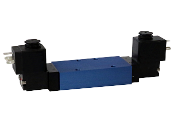




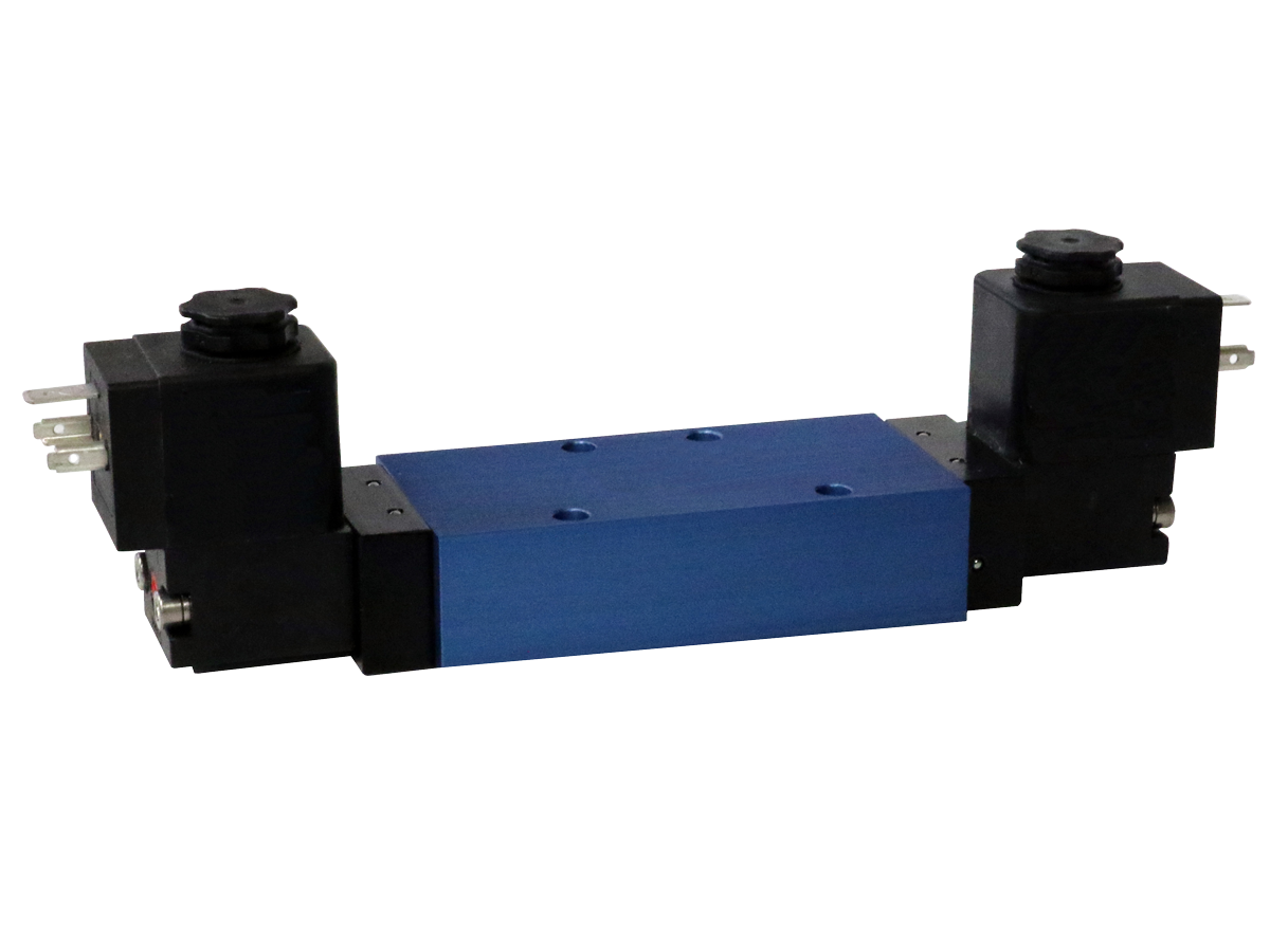
ISO 5599-1 Valves I15, I20, & I45 Series
 Operating Instructions
Product Catalog
Product Catalog - Explosion-Proof & Intrinsically Safe
Operating Instructions
Product Catalog
Product Catalog - Explosion-Proof & Intrinsically Safe
- Wide variety of options and operators available
- Conforms to ISO 5599/1specifications for size 1, 2 and 3
- SIL Certified
- Additional models available, please view downloadable literature
loading...
loading...
Product Overview
The Automatic Valve I15, I20, and I45 Series are base-mount spool directional control valves designed and manufactured to the ISO 5599/1 interface standard for pneumatic valve sizes 1, 2, and 3. Interchangeable with any ISO 5599/1-conforming sub-base or manifold regardless of brand, these valves deliver drop-in replacement capability and broad compatibility with existing machine designs. The three series cover 5/2 (4-way 2-position) and 5/3 (4-way 3-position) valve functions with spring return, detented, and spring-centered configurations.
Flow capacity scales with ISO size: the I15 Series (ISO Size 1) delivers 1.5 Cv (1,480 l/min) in the 5/2 function; the I20 Series (ISO Size 2) provides 2.0 Cv (1,970 l/min); and the I45 Series (ISO Size 3) reaches 4.5 Cv (4,430 l/min). The 5/3 three-position function is rated at 1.2, 1.6, and 3.5 Cv respectively. All three series operate on 35 to 150 psig supply (345 to 1,030 kPa for 5/3 center positions requiring 50 psig minimum), covering the standard pneumatic pressure range used in automation equipment worldwide.
A wide variety of actuation options are available across all three ISO sizes: solenoid-pilot operated (single and double), air pilot (single and double), hand lever, and push-button manual operators. Explosion-proof CSA/FM and ATEX coil options, intrinsically-safe versions, and an ultra-low-wattage 0.7-watt coil option extend the I Series to hazardous locations and energy-sensitive applications. SIL certification confirms suitability for safety-related pneumatic control architectures.
Key Engineering Features
- ISO 5599/1 Conformance (Sizes 1, 2, and 3) - Valves conform to the ISO 5599/1 interface standard, providing physical interchangeability with ISO-rated sub-bases and manifolds from any supplier. This protects existing machine designs when valves are replaced or upgraded.
- SIL Certified - I Series valves carry SIL certification for integration into safety-related pneumatic control systems where functional safety compliance is required by machine safety standards.
- Three ISO Sizes with Matched Flow Capacity - I15 (Size 1, 1.5 Cv), I20 (Size 2, 2.0 Cv), and I45 (Size 3, 4.5 Cv) in 5/2 function. Selecting the correct ISO size ensures the valve matches sub-base port dimensions while delivering adequate flow for the actuator.
- 5/2 and 5/3 Functions in One Platform - Single 5/2 (spring return), double 5/2 (detented), and 5/3 three-position (block center, exhaust center, pressure center) configurations are available within the same body, simplifying spare parts management.
- Wide Operator Selection - Solenoid-pilot (single and double), air pilot, hand lever, and push-button operators are available across all three ISO sizes. Operators may be combined (e.g., solenoid on one end, air pilot on the other) for specialized circuit functions.
- Explosion-Proof and Intrinsically-Safe Options - CSA and FM approved explosion-proof coils and ATEX explosion-proof coils are available for hazardous area installations. Intrinsically-safe versions are available for 24 VDC applications where ignition energy must be limited at the coil.
- Ultra-Low-Wattage Coil Option (0.7 Watts) - The LL2 option provides a lowest-wattage coil for energy-conscious designs and battery-powered or low-power-budget control systems. Paired with an extended turn-locking override.
- Internal or External Pilot Supply - Pilot is internally supplied when inlet pressure is 35 to 150 psig. External pilot option (Option B) extends the inlet range to vacuum, allowing independent pilot supply when inlet pressure is below 35 psig.
- Hermetically Sealed Integral Coil - Solenoid coils are hermetically sealed as integrally molded watertight units, providing protection against moisture ingress and coil burnout risk from condensation in humid environments.
- Treated Buna-N and Fluoroelastomer Seal Options - Standard treated Buna-N (NBR) seals provide extended life in compressed air service. Fluoroelastomer (FPM/FKM) Option A seals are available for chemically aggressive environments or elevated temperature service.
Technical Specifications
General Specifications
| Parameter | Specification |
| Valve Series | I15 (ISO Size 1), I20 (ISO Size 2), I45 (ISO Size 3) |
| Standard | ISO 5599/1 Sizes 1, 2, and 3 |
| Valve Functions | 5/2 Single (NC, spring return); 5/2 Double (detented); 5/3 Block Center; 5/3 Exhaust Center; 5/3 Pressure Center |
| Construction | Spool |
| Body Type | Base Mount (valve body only, requires ISO 5599/1 compatible sub-base or manifold) |
| Operating Pressure (2-Position) | 35 to 150 psig (240 to 1030 kPa) |
| Operating Pressure (3-Position) | 50 to 150 psig (345 to 1030 kPa) |
| External Pilot Option B Range | Vacuum to 35 psig inlet; 35 to 150 psig external pilot |
| Flow Media | Air or inert gas; lubrication not required but recommended to maximize service life |
| Manual Override | Push non-locking (standard); Extended push non-locking (Option 5); Turn-locking (Option LL2) |
| Seal Material | Treated Buna-N (NBR, standard); Fluoroelastomer FPM/FKM (Option A) |
| Valve Body Material | Aluminum |
| Filtration | Air line filtration recommended; lubrication not required; if used, specify medium aniline point lubricant (82 C to 99 C / 180 F to 210 F) |
Temperature Ratings
Temperature ratings apply to both ambient and media conditions. High-temperature coil Option CT extends the ambient limit to 82 C (180 F).
| Configuration | Ambient Temperature | Media Temperature |
| Standard Buna-N Seals (all solenoid functions) | 18 to 50 C (0 to 123 F) | 18 to 50 C (0 to 123 F) |
| Fluoroelastomer Seals Option A (all solenoid functions) | 18 to 50 C (0 to 123 F) | 18 to 50 C (0 to 123 F) |
| High Temp Coil Option CT (Buna-N or FPM seals) | 18 to 82 C (0 to 180 F) | 18 to 82 C (0 to 180 F) |
Important: For media temperatures below 4 C (40 F), compressed air must be free of water vapor to prevent ice formation within the spool valve.
Electrical Data (Solenoid Pilot Valves)
All solenoid coils are rated for 100% continuous duty. Power values are nominal at rated voltage; voltage tolerance is +/-10% of nominal.
| Voltage | Power Consumption |
| 12 VDC (-DA) | 4.8 W |
| 24 VDC (-DB) | 4.5 W |
| 110/120 VAC 50/60 Hz (-AA) | 6.9 / 6.5 VA |
| 220/240 VAC 50/60 Hz (-AB) | 6.4 / 6.8 VA |
| 125 VDC (-AA suffix with Y coil) | 3.4 W |
| Ultra-Low Watt Option LL2 | 0.7 W (24 VDC, with extended turn-locking override) |
Electrical Connection Options
| Connection Type | Coil Code |
| DIN 43650 Form B (Weather-Proof, NEMA 4X, standard) | X |
| 18" Flying Leads (Weather-Proof, NEMA 4X) | G |
| 1/2" Conduit with 30" Leads (Weather-Proof, NEMA 4X) | C |
| 1/2" Conduit High Temp to 82 C (NEMA 4X) | CT |
| Explosion-Proof 1/2" Conduit CSA and FM (NEMA 4/4X/7C/7D/9) | Y |
| ATEX Explosion-Proof 3m Cable and Strain Relief | Z |
| Intrinsically-Safe (24 VDC only, Class I Groups A-D, Class II-III Div.1 T5) | consult factory |
Flow Performance Data
Flow performance for I Series valves at standard operating conditions. Values shown are for 5/2 single and 5/3 functions. External pilot Option B reduces minimum inlet pressure to vacuum.
| Series | ISO Size | Function 5/2 Cv | Flow 5/2 (l/min) | Function 5/3 Cv | Flow 5/3 (l/min) | Weight kg (lb) |
| I15 | 1 | 1.5 | 1480 | 1.2 | 1154 | 0.4 (0.9) |
| I20 | 2 | 2.0 | 1970 | 1.6 | 1537 | consult catalog |
| I45 | 3 | 4.5 | 4430 | 3.5 | 3455 | consult catalog |
Certifications & Compliance
| Certification/Standard | Detail |
| ISO 5599/1 Conformance | Valve bodies and interface dimensions conform to ISO 5599/1 for Sizes 1, 2, and 3, ensuring physical interchangeability with any ISO 5599/1-compatible sub-base, manifold, or accessory module. |
| SIL Certification | I Series valves are SIL certified for use in safety-related pneumatic control systems. Consult Automatic Valve for SIL level and application-specific documentation. |
| CSA Approval (Explosion-Proof) | Explosion-proof coil Option Y is CSA approved (C22.2 and UL STD 429) for Class I Division 1 Groups A, B, C, D; Class II Groups E, F, G; Class III; T4; Ta = -20 to +60 C; NEMA 4, 4X, 7C, 7D, 9. |
| Factory Mutual (FM) Approval | Factory Mutual approved for explosion-proof installations in Class I Division 1 hazardous locations in conjunction with the Y explosion-proof coil option. |
| ATEX Compliance (Explosion-Proof) | ATEX explosion-proof coil Option Z: Ex m II T5 PTB 03 ATEX 2018 X; Ex II 2 G EEx m II T5; Ex II 2 D IP65 T95 C. |
| Intrinsic Safety | Intrinsically-safe versions available for Class I Groups A-D; Class II Groups E-G; Class III Division 1 T5; 24 VDC only. Consult factory for approval documentation. |
| CE Marking | Products meet CE requirements for EMF and Low Voltage Directives for industrial use within the European Union. |
Typical Applications & Industries
Automotive Assembly and Body Shop Automation
- Welding fixture actuation and clamping systems where double 5/2 detented valves maintain cylinder position even when the control signal is removed, reducing energy consumption on long-dwell tooling.
- Paint booth conveyor and part positioning systems using I45 high-flow valves to drive large-bore cylinders at speeds compatible with production rate targets.
- Spot weld gun opening and closing circuits that require fast, consistent 5/2 switching with high cycle durability to meet automotive body shop throughput demands.
- Transfer line and rotary index table control using I20 and I45 Series with 5/3 block-center function to hold cylinder position at mid-stroke when the valve is de-energized.
Plastics and Rubber Processing
- Injection molding machine tie-bar clamp and ejector circuits using ISO-conforming valves for standardized machine architecture and simplified spare parts management across multiple machines.
- Blow molding mold open/close and parison control systems using I45 high-flow valves to meet fast cycle requirements in high-output production environments.
- Rubber vulcanization press actuation where double 5/2 detented valves maintain press position independently of the control signal during the curing dwell period.
- Thermoforming machine platen actuation and sheet clamp control using 5/3 pressure-center configurations that maintain pressure on the sheet during the forming cycle.
Material Handling and Conveying
- Pallet transfer, diverter gate, and pushrod systems on automated conveying lines where I20 or I45 Series valves provide the flow capacity required for large-bore actuators.
- Automated storage and retrieval systems with multiple pneumatic axes benefiting from the ISO manifold-mount format and common sub-base standardization.
- Sorting equipment with high-speed diverter actuators that require 5/2 spring-return valves for fail-safe retraction on loss of signal.
- Palletizing and depalletizing machinery using double solenoid 5/2 configurations for bidirectional cylinder control without a return spring, maximizing force in both directions.
Hazardous Location and Process Industries
- Oil and gas upstream and midstream facilities requiring CSA/FM explosion-proof solenoid valves on instrument air-operated equipment in Class I Division 1 classified areas.
- Chemical plant reactors and storage systems using ATEX Zone 1 approved I Series valves for process air actuation in European-standard hazardous area installations.
- Grain handling and milling facilities in Class II Group G locations where dust explosion risk requires rated explosion-proof solenoid coils.
- Paint spray booths and solvent processing lines in Class I Division 1 environments where standard electrical equipment is prohibited.
Food Processing and Packaging
- Filling machine cylinder actuation and product gate control where washdown-compatible solenoid coil enclosures and corrosion-resistant materials are required.
- Slicing, portioning, and forming equipment that demands reliable 5/2 and 5/3 valve functions with high cycle counts and consistent response times.
- Packaging line conveyors, case erectors, and labeling systems where ISO 5599/1 interchangeability allows cross-brand manifold standardization within a facility.
- Controlled atmosphere and refrigerated processing areas where ambient temperature stays within the -18 to +50 C (0 to 123 F) operating range of standard I Series valves.
General Machine Building and OEM Equipment
- Multi-axis automation cells using ISO 5599/1 manifolds to mount I15, I20, or I45 valves in configurations that match actuator sizes and flow requirements per axis.
- Press automation and stamping machinery using 5/3 block-center valves to hold the ram in position and prevent drift during tool setup without consuming compressed air.
- Test and measurement equipment requiring consistent, repeatable switching performance across extended calibration intervals.
- Custom machinery projects where ISO 5599/1 conformance ensures valve interchangeability with sub-bases and manifolds from the OEM's standard supplier regardless of Automatic Valve's production schedule.
Ordering and Model Number Configuration
The I Series model number encodes the valve size (I15/I20/I45), body type, port location, function, operator type, voltage, and options. Air pilot models use AAAR suffix; solenoid models specify coil voltage with the -** voltage code. Options are appended as suffixes after the voltage code.
|
I Series Model Number Structure:
I15 / I20 / I45 - Series and ISO Size | 00 - Body Type and Port Location (0 = Base Mount, 0 = Standard Port) | A - Function (A = 5/2 Single; B = 5/2 Double; C = 5/3 Block; D = 5/3 Exhaust; E = 5/3 Pressure) | A - Operator 1 (A = Air Pilot; X = Solenoid Pilot; B = Hand Lever; E = Push Button) | X - Center Operator (X = Spring; D = Detent; for 5/3 configurations) | R - Operator 2 (R = Spring Return; X = no second op) | DB - Voltage Code (-AA = 110/120 VAC; -AB = 220/240 VAC; -DA = 12 VDC; -DB = 24 VDC)
Air Pilot 5/2 Single: I1500AAAR (I15) / I2000AAAR (I20) / I4500AAAR (I45) Solenoid 5/2 Single: I1500AAXR-DB (I15, 24 VDC) / I2000AAXR-AA (I20, 120 VAC) Solenoid 5/3 Block: I1500CBXDX-DB / I2000CBXDX-AA / I4500CBXDX-AA |
Voltage codes: -AA = 110/50 or 120/60 Hz; -AB = 220/50 or 240/60 Hz; -DA = 12 VDC or 24 Hz AC variants; -DB = 24 VDC.
Options appended after voltage code: A = Fluoroelastomer seals; B = External pilot supply; C = Conduit coil; CT = High temp conduit coil (to 82 C); D = Dustproof; G = 18" flying leads; LL2 = 0.7 W low-wattage coil with extended turn-locking override; Y = Explosion-Proof CSA/FM; Z = ATEX explosion-proof; 5 = Extended push non-locking override.
Sub-base and manifold models for I15/I20/I45 are ordered separately. Sub-base models: I15 = 7107-501/7107-502; I20 = 7112-501/7112-502; I45 = 7129-501/7129-502. Add W suffix for G (BSPP) thread ports on sub-bases and manifolds.
Not all options are available for all models. Refer to catalog or contact Automatic Valve at (248) 474-6761 for option availability matrix.
I Series Flow and ISO Size Summary
| Series | ISO Size | 5/2 Cv | 5/3 Cv | Min Pressure (2-pos) | Min Pressure (3-pos) |
| I15 | 1 | 1.5 | 1.2 | 35 psig | 50 psig |
| I20 | 2 | 2.0 | 1.6 | 35 psig | 50 psig |
| I45 | 3 | 4.5 | 3.5 | 35 psig | 50 psig |
Sub-Base Port Size Options
| Series | Sub-Base Model | Work Ports 2 and 4 | Supply/Exhaust Ports 1,3,5 |
| I15 (ISO 1) | 7107-501 | 1/4" | 1/4" |
| I15 (ISO 1) | 7107-502 | 3/8" | 3/8" |
| I20 (ISO 2) | 7112-501 | 3/8" | 3/8" |
| I20 (ISO 2) | 7112-502 | 1/2" | 1/2" |
| I45 (ISO 3) | 7129-501 | 1/2" | 1/2" |
| I45 (ISO 3) | 7129-502 | 3/4" | 3/4" |
Accessories
ISO 5599/1 Sub-Bases
Individual sub-bases mount a single I Series valve body and provide NPT or G thread external port connections. Specify sub-base model to match the required port size. Add W suffix to sub-base model for G (BSPP) thread ports.
ISO 5599/1 Manifold Bases
Multi-station manifold bases accommodate multiple I Series valves in a common assembly with shared supply and exhaust galleries. Available for I15, I20, and I45 with multiple station counts. Manifold model prefix: A7107 (I15), A7113 (I20), 7130 (I45).
DIN 43650 Form B Connectors
Weather-proof DIN 43650 Form B connectors for solenoid coil wiring. Compatible with the X coil type configuration on I Series solenoid valves. Prewired assemblies and cable grip versions available.
Related Products & Accessories
- Direct Acting Solenoid Valves (K02 Series) - Compact direct-acting poppet solenoid valves for small-bore circuits, 2/2 and 3/2 functions, vacuum to 150 psig. https://www.automaticvalve.com/series/218-direct-acting-solenoid-valves
- SAE Valves (A04, A06, A20 Series) - High-flow spool valves conforming to SAE J2051 for Series 125, 250, and 1000, Cv 2.4 to 22.7. https://www.automaticvalve.com/series/228-sae-valves
- Pilot Poppet Valves (General, Vacuum, Hazardous) - Inline pilot poppet valves for standard, low, and high temperatures with port sizes 1/4" to 1-1/2". https://www.automaticvalve.com/series/2762-pilot-poppet-valves
Frequently Asked Questions (FAQ)
Q: What does ISO 5599/1 conformance mean for machine design?
A: ISO 5599/1 defines the physical interface dimensions, port locations, and fastener hole patterns for pneumatic directional control valves. Conformance means the I15, I20, and I45 valve bodies will physically mount on any ISO 5599/1-rated sub-base or manifold regardless of the sub-base manufacturer, providing true drop-in interchangeability.
Q: How do I choose between the I15, I20, and I45 Series?
A: Select by ISO size based on the actuator bore and cycle time requirements. The I15 (Size 1, 1.5 Cv) suits cylinders up to approximately 50 mm bore at moderate speeds. The I20 (Size 2, 2.0 Cv) handles medium bore cylinders. The I45 (Size 3, 4.5 Cv) is appropriate for large bore or fast-cycle applications. Match the ISO size to the sub-base already installed on the machine.
Q: What is the difference between a 5/2 single and a 5/2 double configuration?
A: A single 5/2 (spring return) has one solenoid operator. When de-energized, the spring returns the spool to the default position, extending or retracting the actuator to the fail-safe position. A double 5/2 (detented) has two solenoid operators and no centering spring. Once shifted by a momentary signal, the valve stays in position until the opposing solenoid is energized, conserving energy on long-dwell applications.
Q: What are the three 5/3 center position options?
A: The block-center (5/3 BC) blocks all five ports when de-energized, holding the actuator in place. The exhaust-center (5/3 EC) connects both work ports to exhaust, allowing the cylinder to float or be moved by hand. The pressure-center (5/3 PC) connects both work ports to supply pressure, maintaining equal pressure on both cylinder sides. Select based on the fail-safe behavior required when the valve loses signal.
Q: What is the external pilot option and when is it needed?
A: Option B provides an external pilot supply port. When the inlet pressure is below 35 psig (240 kPa), the pilot spool cannot shift from internal supply alone. External pilot allows a separate, higher-pressure pilot supply to operate the valve while the inlet carries low or vacuum pressure. This is required for vacuum applications and low-pressure circuits.
Q: What SIL level are I Series valves certified to?
A: I Series valves carry SIL certification. For application-specific SIL level, hardware fault tolerance, and safety function documentation, contact Automatic Valve at (248) 474-6761 or visit automaticvalve.com.
Q: Are I Series valves available with hazardous location approvals?
A: Yes. The Y option provides CSA and FM approved explosion-proof coils rated for Class I Division 1 Groups A-D, Class II Groups E-G, and Class III environments. The Z option provides ATEX explosion-proof coils for Zone 1 hazardous areas. Intrinsically-safe configurations are also available at 24 VDC; consult the factory.
Q: What is the ultra-low-wattage LL2 coil option?
A: Option LL2 specifies a 0.7-watt solenoid coil available for energy-sensitive applications or control systems with limited output current capacity. The LL2 coil includes an extended turn-locking override to allow manual valve position during installation and maintenance. Consult Automatic Valve for voltage availability.
Q: Does air line lubrication affect I Series valve performance?
A: Air line lubrication is not required for I Series valves. If lubrication is used, it should be a medium aniline point petroleum-based lubricant between 82 C and 99 C (180 F to 210 F). Avoid synthetic or phosphate-ester lubricants that may cause elastomer swelling or degradation in Buna-N seals.
Q: Can I Series valves be used in the same sub-base positions as competitor ISO 5599/1 valves?
A: Yes. Because all three series fully conform to ISO 5599/1, they will mount in any sub-base or manifold designed to that standard. Verify that port sizes and electrical connections match the application before substituting.
Q: What is the operating pressure range for 5/3 configurations?
A: Three-position (5/3) configurations require a minimum supply pressure of 50 psig (345 kPa) to ensure positive spool centering by the spring. Two-position (5/2) configurations require 35 psig (240 kPa) minimum supply pressure when using internal pilot.
Q: What is the estimated lead time for I Series valves?
A: Standard manufacturing lead times for quantities of 10 or fewer units are approximately 3 to 4 weeks with shipping available throughout the United States. Contact Automatic Valve at (248) 474-6761 for volume pricing and expedited delivery.
Installation & Maintenance Guidelines
- Mount I Series valve bodies on ISO 5599/1-conforming sub-bases. Verify that the sub-base port size matches the piping and actuator requirements before mounting.
- Torque valve-to-sub-base mounting screws uniformly to the sub-base manufacturer's recommended specification to ensure uniform sealing of the interface O-rings.
- For external pilot Option B, connect a regulated pilot supply of 35 to 150 psig to the external pilot port. Pilot pressure must be maintained to operate the valve when inlet pressure is below 35 psig.
- Supply filtered air at 40 microns or better. Lubrication is not required but, if used, must be a medium aniline point petroleum-based oil to avoid seal degradation.
- For 5/3 three-position configurations, supply pressure must be 50 psig minimum to achieve positive spring centering. Operation below 50 psig may result in the spool not fully returning to center.
- For explosion-proof installations (Option Y), seal all conduit entries within 18 inches of the solenoid enclosure per NEC Article 500. Ensure that the conduit system is rated for the hazardous area classification.
- For ATEX installations (Option Z), verify that the cable gland and cable are rated to IP65 or greater and are compatible with the ATEX zone classification at the installation point.
- Do not restrict exhaust ports on the sub-base or manifold. Exhaust back pressure can prevent spool shifting or cause erratic valve behavior.
- Commissioning: manually actuate each valve using the push non-locking override to verify pneumatic circuit function before energizing solenoids.
- In humid environments, verify that the pilot coil enclosure is oriented to prevent condensate accumulation on the coil. The hermetically-sealed coil design provides moisture protection but correct orientation reduces long-term stress.
Warranty & Global Support
Automatic Valve, a member of the ROSS Controls global family, provides technical support for I Series valve selection, configuration, and system troubleshooting.
For SIL certification documentation, explosion-proof approval certificates, and product data sheets, visit automaticvalve.com or contact Automatic Valve at (248) 474-6761.
Automatic Valve is headquartered in Livonia, Michigan. ROSS Controls global support is available through offices in the USA, Canada, Brazil, Germany, France, United Kingdom, India, China, and Japan.
Operating instructions and product catalogs are available for download on the series page at automaticvalve.com and from authorized Automatic Valve distributors.
Download Catalog: https://www.automaticvalve.com/documents/6611/ISO_Valves_AV-ISO-5599-1_en.pdf
Download Documents
ISO 5599-1 Valves