Technical Tools
Technical Tools is your place to help you better understand your Automatic Valve products. You will find information to help you size valves properly through sizing charts and calculators, how to convert one valve function to another, along with installation and maintenance tips. If you have questions about the use of these tools, please contact Technical Services.
Download PDFSizing Calculator
Find the appropriate valve size for an application by calculating the required Cv (flow coefficient) as shown here and then choose a valve with a Cv equal to or greater than the calculated valve.
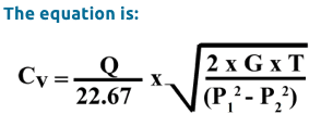
Where:
| Q | = Standard cubic feet of free air (scfm) |
| G | = Gas constant |
| = 1.00 for air | |
| T | = Absolute temperature |
| = Number of Fº + 460 | |
| P 1 | = Valve inlet pressure |
| = psia (pounds per square inch absolute) | |
| = psig (pounds per square inch gage) + 14.7 | |
| P 2 | = Valve outlet pressure |
| = psia (pounds per square inch absolute) | |
| = psig (pounds per square inch gage) + 14.7 |
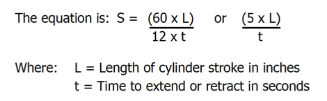
Step 1: Determine the cylinder operating speed, S in ft/min.
Step 2: Determine the volume of free air, Q.
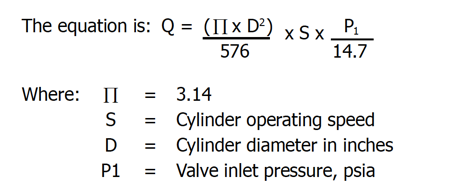
Step 3: Apply Step 1 and 2 results to the Cv formula.
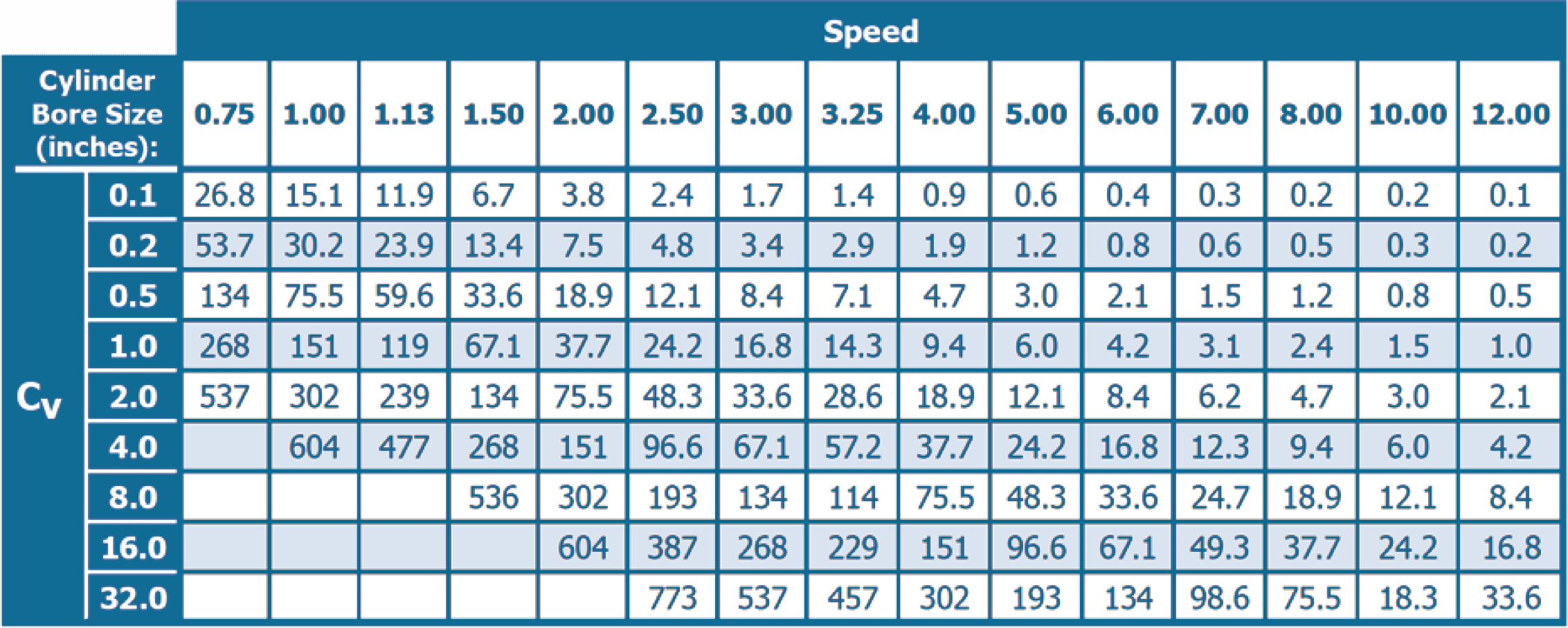
Valve Sizing Chart
The chart below may be used instead of mathematical calculations for close approximations or required valve Cv. The Valve Sizing Chart assumes the following:
- Valve inlet pressure is 80 PSIG.
- Pressure drop through the valve is 10% inlet pressure or 8 PSI.
- There are no line restrictions between the valve and cylinder.
- Distance between the valve and cylinder is 6 feet or less.
Step 1: Calculate the required cylinder speed in inches per second: S = L/T
Where:
- S = Cylinder speed in inches per second
- L = Length of cylinder stroke in inches
- T = Time to extend or retract in seconds
Step 2: Choose the applicable cylinder bore size column.
Step 3: Move vertically down the column to select a speed (inches per second) equal to or greater than the calculated speed and read the required Cv in the left hand column.
Valve Conversion Chart
For:
Single operator spring return valves with balanced spools
Ports:
1 = Supply = P
2 = Outlet =A
3 = Exhaust = EA
4 = Outlet = B
5 = Exhaust = EB
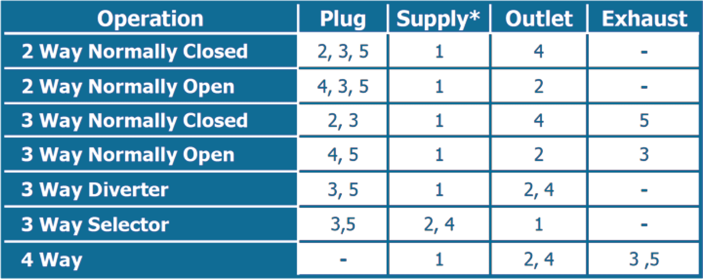
* Minimum operating pressure is 35 psi. Use an external pilot when using a port other than Port 1 for supply or when using a fluid media besides air.