



Manifolds Valve Manifolds
loading...
loading...
Product Overview
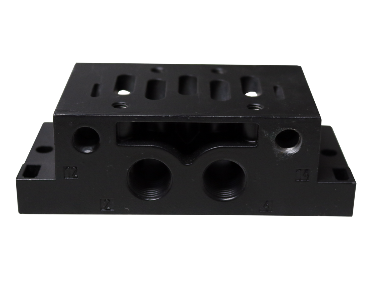
The Automatic Valve Valve Manifolds are multi-station sub-base assemblies that allow multiple directional control valves to share a common supply and exhaust gallery, eliminating the individual fittings, tubing runs, and tee fittings that would otherwise be required to supply and exhaust each valve independently. By integrating the pneumatic supply and exhaust headers into a single machined body, manifolds dramatically reduce system plumbing complexity, minimize potential leak points, and allow the entire valve bank to be mounted, piped, and commissioned as a single unit.
The Series is designed to interface with Automatic Valve directional control valves in the D03 and D05 mounting pattern families, including the popular A7105 and 7107 valve series. With 28 models available spanning from 2 to 10 or more valve stations, and filterable by valve series and number of stations, the series provides the flexibility to configure exactly the manifold size required by the circuit without excess capacity or the cost and footprint penalties associated with oversized assemblies.
Each manifold station presents the valve with four ported connections: supply (P), work ports (A and B), and exhaust (T/R). The shared supply gallery connects all stations in parallel to a single supply inlet, while the shared exhaust gallery collects all exhaust flows to a single exhaust outlet. Work ports at each station connect to the individual actuators served by each valve. This architecture is standard in factory automation, machine building, and process control applications worldwide.
For machine builders and system integrators, the series manifolds provide a repeatable, compact platform for dense valve packing in panels and enclosures, supporting clean installation aesthetics, simplified maintenance access, and straightforward electrical and pneumatic routing. Modular construction and standard bolt patterns enable standardized panel designs that can be applied across multiple machine variants with minimum design rework.
Key Engineering Features
- Multi-Station Sub-Base Design - Shared supply and exhaust galleries eliminate individual valve fittings and tubing, reducing plumbing complexity and potential leak points in multi-valve pneumatic circuits.
- 28 Model Variants - Covers configurations from 2-station to 10+ station manifolds, filterable by valve series (A7105, 7107, and compatible types) and station count to match exact circuit requirements.
- D03 and D05 Pattern Compatibility - Designed to interface with standard D03 and D05 pattern directional control valves, including Automatic Valve A7105 and 7107 Series, ensuring broad compatibility within the Automatic Valve product line.
- Integrated Supply and Exhaust Galleries - Common supply and exhaust headers span all valve stations, delivering equal pressure to each station and collecting all exhaust flows to a single port for centralized silencing or discharge.
- Individual Work Port Access - Each manifold station provides accessible individual work ports (A and B) for connection to actuators, cylinders, or downstream pneumatic components.
- Compact Panel Mounting - Dense station pitch and flat-sided manifold body enable compact valve bank installations in machine control panels, enclosures, and DIN rail or frame-mounted assemblies.
- Configurable Station Count - Selecting the exact station count eliminates wasted manifold capacity and reduces hardware cost, weight, and footprint in the control panel or machine frame.
- Blocking Disk Compatible - Unused stations can be sealed with Blocking Disks, allowing manifolds to be installed in partial configurations and expanded later without manifold replacement.
Technical Specifications
General Specifications
| Parameter | Specification |
| Series | Valve Manifolds |
| Models Available | 28 variants (filter by valve series and number of stations) |
| Station Count Range | 2 stations to 10+ stations |
| Compatible Valve Patterns | D03 and D05 standard mounting patterns |
| Compatible Valve Series | Automatic Valve A7105 Series; 7107 Series; compatible D03/D05 valves |
| Gallery Configuration | Shared supply gallery (P); shared exhaust gallery (T/R); individual work ports (A, B) per station |
| Supply Port Connection | See product catalog for port size and thread specification per model |
| Exhaust Port Connection | See product catalog for port size and thread specification per model |
| Work Port Connection | Per station; see product catalog for port size and thread specification per model |
| Body Material | Machined aluminum alloy |
| Operating Pressure | See product catalog for model-specific ratings |
| Media | Filtered compressed air; dry inert gases |
Certifications & Compliance
| Certification/Standard | Detail |
| CE Compatibility | Manifolds are designed for use with CE-marked Automatic Valve directional control valves within the rated operating parameters of the valve and manifold assembly. |
| Material Compliance | Constructed from aluminum alloy compatible with filtered compressed air and standard industrial pneumatic media. |
Typical Applications & Industries
Automotive Body Shop and Assembly
- Multi-axis robotic welding cells where banks of directional control valves control clamping, part holding, and tool cycling from a single manifold block, reducing wiring and tubing runs to individual valves.
- Paint shop conveyors and carriers with multiple pneumatic functions (door openers, hold-down clamps, part locators) served from a common manifold mounted on the carrier body.
- Engine and transmission assembly lines with valve banks on assembly fixtures controlling multiple pneumatic tools simultaneously from compact manifold-mounted valve arrays.
Industrial Automation and Machine Building
- Automated assembly machines with 4 to 10 or more pneumatic cylinder axes controlled from a single manifold valve bank, simplifying panel design and reducing machine build time.
- Pick-and-place gantry systems where multiple gripper, clamp, and lift functions are fed from a centralized valve manifold, minimizing compressed air plumbing across the machine frame.
- Special purpose machines for pressing, testing, marking, and inspection where valve manifolds standardize the pneumatic control architecture across multiple machine configurations.
Packaging Machinery
- Form-fill-seal packaging machines with 6 to 10 valve stations controlling film feed, forming, sealing, and cutting functions from a single compact manifold assembly.
- Case erectors and carton sealers with multi-function valve banks mounted on the machine frame, reducing the external tubing and fittings that are prone to damage in high-cycle packaging environments.
- Labeling and marking equipment with valve manifolds controlling label application, product orientation, and reject systems from a consolidated pneumatic control block.
Food and Beverage Processing
- Filling and dosing machines with valve manifolds controlling product flow to multiple filling heads simultaneously from a shared supply manifold with individual station control.
- Conveyor and sortation systems in food plants where stainless-compatible manifold valve banks control diverters, gates, and transfer stations with minimal external tubing in washdown environments.
- Bottling line capper and labeler assemblies using compact valve manifolds in food-grade compliant control enclosures.
Semiconductor and Electronics Manufacturing
- Wafer handling equipment with tight envelope constraints benefiting from dense valve manifold packing to control multiple handling functions within cleanroom-compliant enclosures.
- Surface mount technology (SMT) machines where compact valve banks control nozzle vacuum, component placement, and board transport functions from a single manifold.
Material Handling and Logistics
- Palletizing robots with valve manifolds on the robot arm controlling multiple end-of-arm tooling functions, reducing the pneumatic umbilical bundle running along the robot arm.
- Automated storage and retrieval systems (ASRS) where manifold-mounted valve banks control shuttle and lift pneumatic functions on moving carriage assemblies.
Ordering and Model Number Configuration
The Series includes 28 total variants. Filter on the Automatic Valve website by valve series and number of stations to identify the correct model for your application.
Verify that the selected manifold model matches the valve body mounting pattern (D03 or D05) and the specific Automatic Valve directional control valve series being mounted.
Order Blocking Disks to seal any unused manifold stations in partial-population configurations.
Contact Automatic Valve at (248) 474-6761 for application-specific manifold selection assistance and for information on special configurations or custom station counts.
Sample Manifold Model Selection (Partial List)
| Model Number | Price (USD) | Station Count | Compatible Valve Series |
| 7107-501 | $42.50 | 1 | 7107 Series |
| A7105-002 | $47.25 | 2 | A7105 Series |
| A7105-002W | $47.25 | 2 (W variant) | A7105 Series |
| A7105-004 | $55.25 | 4 | A7105 Series |
| A7105-006 | $82.75 | 6 | A7105 Series |
| A7105-006W | $82.75 | 6 (W variant) | A7105 Series |
Related Products & Accessories
Frequently Asked Questions (FAQ)
Q: What is the advantage of using a valve manifold versus individual valve sub-bases?
A: A manifold integrates the supply and exhaust galleries for all valve stations into a single body, eliminating the need for individual supply fittings, tees, and interconnecting tubing between stations. This reduces the number of potential leak points, decreases assembly time, makes the plumbing layout cleaner and more maintainable, and often results in a more compact overall installation.
Q: How many stations does the series cover?
A: The Series includes 28 model variants spanning from 2-station to 10+ station configurations. Use the filter function on the Automatic Valve website at automaticvalve.com/series/227-manifolds to filter by valve series and station count.
Q: Which directional control valves are compatible with the series manifolds?
A: The Series manifolds are designed for Automatic Valve A7105 and 7107 Series directional control valves and other valves conforming to the D03 or D05 standard mounting pattern. Verify the specific valve body pattern before ordering to ensure dimensional compatibility.
Q: Can I use the manifold with a partial valve population and add valves later?
A: Yes. Unused manifold stations can be sealed with Blocking Disks to prevent leakage. Valves can be added to blocked stations at any time without replacing the manifold body, supporting phased system commissioning and future system expansion.
Q: What is the difference between the standard and W variant models (e.g., A7105-002 vs A7105-002W)?
A: The W variant designation indicates a dimensional or configuration variant of the base model, such as a different work port orientation or an alternative supply inlet configuration. Refer to the product catalog or contact Automatic Valve at (248) 474-6761 to confirm the specific difference for the model variant of interest.
Q: Can the supply pressure be different for each valve station on the manifold?
A: In a standard manifold configuration, all stations share the same supply gallery pressure. To regulate pressure independently at individual stations, a Pressure Regulator sandwich can be installed between the valve and the manifold at the specific station requiring a different pressure.
Q: What port sizes and thread types are available on the supply and exhaust ports?
A: Port sizes and thread types vary by manifold model. Refer to the product catalog available at automaticvalve.com/series/227-manifolds for model-specific port size and thread specifications. Both NPT and metric thread options may be available for select models.
Q: Are the series manifolds suitable for mounting in vertical or horizontal orientations?
A: The manifolds can generally be mounted in any orientation, but the preferred orientation depends on the work port plumbing direction and the accessibility requirements of the specific installation. Consult the installation instructions for the specific model for any orientation restrictions.
Q: What body material are the manifolds made from?
A: The Series manifolds are machined from aluminum alloy, providing a combination of light weight, good corrosion resistance, and machinability for precise port and gallery dimensions.
Q: Can I mix different valve models on the same manifold?
A: All valves mounted on the same manifold must conform to the same mounting pattern (D03 or D05) and the manifold's specific port dimensions. Do not mix valves of different body sizes or port configurations on the same manifold without confirming dimensional compatibility.
Q: Where can I find complete technical data and pricing for all 28 manifold models?
A: Full technical data, dimensions, and pricing for all Series manifold models are available at automaticvalve.com/series/227-manifolds. Contact Automatic Valve at (248) 474-6761 for application assistance or custom configuration inquiries.
Q: What is the maximum operating pressure for the series manifolds?
A: Refer to the product catalog for model-specific maximum operating pressure ratings. The manifold pressure rating and the valve pressure rating must both be respected; the lower of the two values governs the system working pressure limit.
Installation & Maintenance Guidelines
- Depressurize and lockout/tagout the pneumatic system before installing or modifying any manifold assembly.
- Verify that the selected manifold model is compatible with the specific directional control valve model by confirming matching mounting pattern (D03 or D05) and bolt hole positions.
- Clean all manifold port faces and mounting surfaces before installing valves. Remove machining chips, burrs, or contaminants that could damage valve body seals.
- Install Blocking Disks on all unused valve station ports before pressurizing the system.
- Torque all valve mounting bolts to the specification provided in the valve and manifold installation instructions. Use a cross-tightening pattern to ensure even sealing compression.
- Install silencers or exhaust manifold connections at the exhaust port(s) to comply with noise regulations and prevent contamination entry.
- Use properly rated pneumatic tubing and fittings on all work ports. Ensure fitting thread type matches the manifold work port thread specification.
- Apply supply pressure gradually at commissioning and check for leaks at all valve mounting faces and port connections before proceeding to full operating pressure.
- Label all work port connections on the manifold and document the circuit schematic for future maintenance reference.
- Schedule periodic inspection of valve-to-manifold seal faces for signs of leakage, which can indicate worn valve body O-rings requiring valve service.
Warranty & Global Support
Automatic Valve products are backed by a one-year warranty covering defects in material and workmanship from the date of purchase.
Technical support is available through Automatic Valve at (248) 474-6761 or through the contact form at automaticvalve.com.
Automatic Valve is a member of the ROSS Controls global family, with support resources available through ROSS Global offices worldwide.
For manifold selection assistance, compatible valve recommendations, and replacement parts, visit automaticvalve.com or contact your authorized Automatic Valve distributor.
Download Catalog: https://www.automaticvalve.com/documents/415/AV_Compact_L-Series_Manual-Mechanical_Valves_AV-C-MMV_en.pdf
Download Documents
Manifolds