




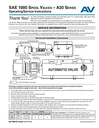
SAE 1000 Spool Valves Operating and Service Instructions (A20 Series)
Overview of the SAE 1000 Spool Valve Operating Manual
The SAE 1000 Spool Valves Operating/Service Instructions document (Form AV-SAE-1000-OI) is the official service and operating guide for Automatic Valve's A20 Series pneumatic spool valves. The A20 Series represents the largest valve in the Automatic Valve SAE spool valve family, offering significantly higher flow capacity than the SAE 125 (A04) and SAE 250 (A06) models. Designed for heavy-duty industrial pneumatic applications, the SAE 1000 class valve delivers exceptional performance in systems demanding large volume air control.
This comprehensive document covers the complete service kit installation process, solenoid wiring configurations across multiple connector types, external pilot field conversion procedures, and important safety cautions and warnings. It is intended for use alongside the A04 and A06 Series operating instructions, as certain service procedures for the A20 valve reference those companion documents directly.
Intended Audience and Related Documents
This manual is designed for trained and experienced pneumatic equipment technicians. Automatic Valve requires that only qualified personnel service the A20 Series valve. The document should be read completely before beginning any service work and saved for future reference. Because the A20 Series valve incorporates an A04 pilot operator (for solenoid valve configurations), technicians should also have access to the SAE 125 Series operating/service instructions for complete A04 pilot operator servicing guidance.
Service Kit Installation Instructions for SAE 1000 (A20 Series)
The A20 Series service procedure is unique among the Automatic Valve SAE spool valve family because it involves servicing both the main A20 valve body and, for solenoid configurations, the A04 pilot operator mounted on top. The document provides clear instructions for both aspects of the service, referencing the SAE 125 Series instructions for the A04 pilot valve servicing steps.
Pre-Service Safety Requirements
Before servicing the SAE 1000 spool valve, follow all required safety procedures: implement appropriate lock-out/tag-out procedures per OSHA 1910.147 and EN 1037, turn off electrical power to the valve, remove the valve from all electrical and air power sources, and ensure all stored air power is fully exhausted. Do not attempt to service the valve if you are not familiar with lock-out/tag-out procedures. These precautions are mandatory to prevent injury from unexpected pressurization or electrical energization during service.
Step-by-Step Service Procedure
Begin by removing the plate (for air pilot configurations) or the A04 operating valve (for solenoid valve configurations). For solenoid valves, follow the separate Service Kit Installation Instructions for the A04 as described in the SAE 125 Series operating/service instructions.
To service the A20 valve body, follow the Service Kit Installation Instructions for the A06 as described in the SAE 250 Series operating/service instructions, with one important exception: on Step 14, torque cap screws to 9.0 N-m (80 in-lbs) ±10% instead of the A06's 6.7 N-m specification. Replace the gasket between the A20 body and the plate or A04 operating valve if necessary, being careful not to scratch the interface surfaces. Orientate the plate or A04 operating valve to the A20 body by aligning the air pilot holes. Torque cap screws into the body to 6.7 N-m (59 in-lbs) ±10%, alternating the tightening so the cap squeezes evenly onto the body.
Service Kit Contents and Part Numbers
The A20 Series service kits contain components for rebuilding the complete valve assembly. The single operator kit (K-A20-SGL) includes 12 tee-seals, 2 gaskets, and 6 piston seals. The double operator kit (K-A20-DBL) contains the same quantities. These larger kits reflect the A20's bigger body size and the need to service both the main valve body and the A04 pilot operator components. Air line lubrication is not required but is recommended to maximize service life, using oils compatible with the seal material, with ISO 32 or lighter viscosity, and an aniline point between 82°C (180°F) and 99°C (210°F).
Wiring Configurations for the A20 Series
The SAE 1000 operating instructions include the same comprehensive wiring diagrams as the smaller SAE spool valve models, covering seven distinct connector configurations. These include 4-pin Micro, 5-pin Micro, and 5-pin Mini connector formats in GM, Ford, and Chrysler wiring standards.
Each wiring configuration provides a clear schematic showing solenoid A and solenoid B connections with color-coded wire identification and a pin-out table mapping each pin number to its corresponding solenoid terminal. For single solenoid valves, the Sol B pin-out should be followed. Wire colors referenced include red, black, brown, green, blue, red/white, red/black, and red/yellow. These comprehensive wiring tables allow technicians to correctly wire the A20 Series valve across diverse installation environments and connector standards.
External Pilot Field Conversion for SAE 1000
The A20 Series valve can be field-converted from internal pilot supply to external pilot supply when application conditions require a separate pilot pressure source. The conversion process is straightforward: remove the valve from the sub-base and turn it upside down. Remove the 1/16 NPTF pipe plug from the external pilot supply port and install it in the internal pilot supply port. Connect the air supply to the external pilot supply port in the base.
For the A20 Series specifically, the external pilot supply port uses a 1/4 NPTF fitting, which is larger than the 1/8 NPTF fitting used on the A04 and A06 Series, reflecting the A20's larger flow capacity requirements. The ground wire configuration follows the same standard: for AC solenoids, the ground wire is screwed to the inside of the cap; for DC solenoids, the ground wire is capped.
Torque Specifications and Assembly Details
Proper torque values are critical for the safe and reliable operation of the SAE 1000 spool valve. The A20 Series has several key torque specifications that technicians must follow carefully during reassembly:
Body screws (1/4-20) should be torqued to 6.7 N-m (59 in-lbs) ±10%. Caps retained with M3 screws are torqued to 1.2 N-m (9 in-lbs) ±10% for the A04 pilot operator component. Caps retained with 3/8-16 screws on the A20 body are torqued to 9.0 N-m (80 in-lbs) ±10%. Coil retention nuts should be tightened per the A04 service procedure. All screws should be tightened in an alternating pattern to ensure even compression of gaskets and seals.
Filtration, Lubrication, and Safety Warnings
The ROSS Group recommends a 5-micron rated filter for the air supply. While air line lubrication is not required, it is recommended to maximize service life using compatible petroleum-based oils with oxidation inhibitors. Oils with phosphate-type additives must be avoided as they can harm polyurethane components and potentially lead to valve failure.
The cautions and warnings section covers all essential safety information: pre-installation and service lockout requirements per OSHA 1910.147, filtration and lubrication best practices, intake and exhaust restriction warnings, and safety application requirements for mechanical power presses and other hazardous machinery. Exhaust silencers must be properly sized and resistant to clogging to prevent back pressure that can cause erratic valve action.
Warranty for SAE 1000 Spool Valves
The ROSS Group provides a standard one-year warranty from the date of purchase on all SAE 1000 spool valves, covering defects in material and workmanship. Filters, regulators, and lubricators carry an extended seven-year warranty period. The warranty does not cover misuse, misapplication, improper maintenance, modification, or tampering. Products requiring warranty evaluation must be returned freight prepaid to the ROSS Group for inspection and determination.
Frequently Asked Questions
How does servicing the SAE 1000 A20 Series differ from the SAE 125 and SAE 250 models?
The SAE 1000 A20 Series valve is a larger, two-part assembly that combines an A20 main valve body with an A04 pilot operator (for solenoid configurations) or an air pilot plate. Servicing requires referencing both the SAE 125 Series instructions (for the A04 pilot operator) and the SAE 250 Series instructions (for the A20 body, which follows the A06 procedure with a higher cap screw torque of 9.0 N-m vs. 6.7 N-m). The A20 service kit also contains more components — 12 tee-seals and 6 piston seals — compared to the 6 tee-seals in the smaller models.
What size fitting does the SAE 1000 external pilot supply port use?
The A20 Series SAE 1000 valve uses a 1/4 NPTF fitting for the external pilot supply port, which is larger than the 1/8 NPTF fitting used on the A04 and A06 Series valves. This larger fitting size accommodates the higher flow requirements of the SAE 1000 valve. The internal pilot port uses the same 1/16 NPTF pipe plug for field conversion.
What are the critical torque specifications for the A20 Series valve?
The A20 Series has several critical torque values: body screws (1/4-20) at 6.7 N-m (59 in-lbs) ±10%, A20 body cap screws (3/8-16) at 9.0 N-m (80 in-lbs) ±10%, and A04 operator cap screws (M3) at 1.2 N-m (9 in-lbs) ±10%. Always alternate the tightening pattern so components seat evenly. Using a calibrated torque wrench is essential for proper assembly.
Can I service the A20 valve body without servicing the A04 pilot operator?
Yes, the A20 valve body and A04 pilot operator can be serviced independently if only one component needs attention. However, Automatic Valve recommends inspecting both components during any service interval to ensure overall system reliability. If the A04 pilot operator is functioning properly, you can focus on the A20 body service alone using the A06 procedure with the modified 9.0 N-m cap screw torque.
What lubrication is recommended for SAE 1000 spool valve service?
Automatic Valve recommends lubricating all designated components with a thin film of compatible lubricant during service. Oils should be petroleum-based with oxidation inhibitors, an ISO 32 or lighter viscosity, and an aniline point between 82°C (180°F) and 99°C (210°F). Components marked with '+' in the assembly drawing should look wet with no excess lubricant visible. Avoid oils with phosphate-type additives, which can damage polyurethane seals.