




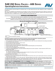
SAE 250 Spool Valves Operating and Service Instructions (A06 Series)
Overview of the SAE 250 Spool Valve Service Manual
The SAE 250 Spool Valves Operating/Service Instructions document (Form AV-SAE-250-OI) is the official service and maintenance guide for Automatic Valve's A06 Series pneumatic spool valves. The A06 Series is an SAE 250 class valve designed for higher flow capacity applications compared to the smaller SAE 125 (A04) series, while maintaining the same premium build quality and ease of serviceability that Automatic Valve is known for.
This manual provides complete service kit installation procedures, detailed solenoid wiring diagrams for multiple connector types, external pilot field conversion instructions, manifold base assembly guidance, and comprehensive safety cautions and warnings. It is an essential resource for plant maintenance teams, pneumatic technicians, and OEM integrators working with SAE 250 class directional control valves.
Document Scope and Intended Audience
This document is intended for trained and experienced pneumatic equipment professionals. Before performing any service on the A06 Series valve, the manual should be read in full and retained for future reference. A general user manual with more detailed information on Automatic Valve products is available online at www.automaticvalve.com. For questions about installation or servicing, technicians should contact Automatic Valve directly or an authorized AV distributor.
Service Kit Installation Procedure for SAE 250 (A06 Series)
The manual's primary content is a detailed, step-by-step service kit installation procedure for rebuilding the A06 Series spool valve. The procedure is designed to be performed by qualified technicians and covers safe de-energization, disassembly, component replacement, lubrication, and reassembly with proper torque specifications.
Safety and Lockout Procedures Before Service
All service work on the SAE 250 spool valve begins with mandatory safety procedures. Technicians must follow appropriate lock-out/tag-out procedures as defined by OSHA 1910.147 and EN 1037. Do not attempt to service a valve without familiarity with these procedures. Turn off electrical power to the valve, remove the valve from all electrical and air power sources, and ensure all stored air power is fully exhausted before beginning disassembly. These steps prevent accidental actuation during service, which could result in serious injury.
Disassembly and Component Replacement Steps
With the valve safely isolated, remove the end caps by extracting the 2 socket head cap screws. Gently push internal components out of the valve body. Clean the spool thoroughly with a clean cloth. Discard the spring on single spring return models only.
Lubricate all designated components (marked with '+' in the assembly drawing) with a thin film of compatible lubricant — components should look wet with no excess lubricant visible. Replace components in the correct sequence: alternate tee-seals and spacers until all 6 are installed, insert the retainer and piston into the end cap, insert the O-ring in the end cap, and replace the spring (single spring return models only). Orientate the spool as shown in the assembly diagram. Verify that the rubber plug is still present in the body for 9A operator configurations.
Reassembly and Torque Specifications
Orientate the caps by aligning the pilot hole in the valve body with the pilot hole in the cap. For external pilot configurations, the pilot hole is covered — refer to the field conversion section. Torque cap screws to 6.7 N-m (59 in-lbs) ±10%, alternating the tightening of screws so that the cap squeezes evenly onto the body. Replace the housing gasket if necessary and torque housing screws to 4.8 N-m (42 in-lbs) ±10%, taking care not to scratch the interface surface. Replace the body-to-base gasket if necessary and torque body-to-base screws (5/16-18) to 13.7 N-m (121 in-lbs) ±10%.
Available Service Kit Part Numbers
Service kits for the A06 Series are available in both Buna-N and Fluoroelastomer seal materials. The single operator kit (K-A06-SGL for Buna-N or K-A06-SGL-A for Fluoroelastomer) contains 6 tee-seals, 1 gasket, 1 piston seal, and 1 spring. The double operator kit (K-A06-DBL or K-A06-DBL-A) contains 6 tee-seals, 2 gaskets, 2 piston seals, and no spring. Always use genuine Automatic Valve service kits to ensure proper fitment and maintain warranty coverage.
Solenoid Wiring Diagrams and Connector Options
The SAE 250 operating instructions include complete wiring schematics for the A06 Series valve across seven distinct connector configurations. These include 4-pin Micro, 5-pin Micro, and 5-pin Mini connector styles in GM, Ford, and Chrysler wiring standards. Each wiring diagram identifies solenoid A and solenoid B connections, wire color codes (red, black, brown, green, blue, red/white, red/black, red/yellow), and a pin-out table that maps each numbered pin to the corresponding solenoid lead.
For single solenoid applications, technicians should follow the Sol B pin-out. The document provides clear visual schematics for each configuration, making it straightforward to wire the valve correctly regardless of which connector standard is in use. Correct wiring is essential for reliable valve operation and to prevent solenoid damage or electrical faults.
External Pilot Supply Field Conversion
The SAE 250 spool valve can be field-converted from standard internal pilot supply to external pilot supply. This conversion is needed when operating the valve at pressures outside the internal pilot operating range or when an independent pilot pressure source is required for the application.
To convert, remove the valve from the sub-base and invert it. Remove the 1/16 NPTF pipe plug from the external pilot supply port and install it in the internal pilot supply port. Connect the external air supply to the pilot supply port in the base. The A06 Series uses a 1/8 NPTF fitting for the external pilot supply. The manual also notes the ground wire configuration: for AC solenoids, the ground wire is screwed to the inside of the cap; for DC solenoids, the ground wire is capped.
Assembly to Manifold Base (Models 413 and 416)
The document includes detailed assembly instructions for mounting SAE 250 spool valves to manifold bases. Two manifold configurations are covered — Model 413 and Model 416 — each with distinct assembly sequences.
For Model 413 assemblies, O-rings are placed in counterbores in the base, and then base-to-base assembly is completed using screws, washers, and nuts. For Model 416 assemblies, the process adds end cap O-ring installation and cap-to-base assembly as intermediate steps. Both configurations follow numbered step sequences with visual references for proper O-ring placement and hardware installation. End caps are specific to the A06 model and must be oriented correctly for proper sealing.
Filtration, Lubrication, and Safety Warnings
Automatic Valve recommends a 5-micron rated filter for the air supply to prevent contaminants from interfering with valve performance. Air line lubrication is not required but is recommended to extend service life. Compatible lubricants are petroleum-based oils with oxidation inhibitors, an ISO 32 or lighter viscosity, and an aniline point between 82°C (180°F) and 99°C (210°F). Avoid oils with phosphate-type additives, which can damage polyurethane components.
The cautions and warnings section covers pre-installation and service safety, filtration and lubrication guidelines, intake and exhaust restriction warnings, and safety application requirements. All products must be used within specification limits. Exhaust ports should never be restricted in ways that reduce flow below the valve's exhaust capacity. Silencers must be properly sized and maintained to prevent clogging, which can cause back pressure and erratic operation.
Warranty Coverage for SAE 250 Spool Valves
SAE 250 spool valves from Automatic Valve carry a one-year warranty from the date of purchase as part of the ROSS Group standard warranty program. Filters, regulators, and lubricators are covered for seven years. The warranty covers defects in material and workmanship, and the ROSS Group's obligation is limited to repair, replacement, or refund at their discretion. Warranty claims are void for products subject to misuse, misapplication, improper maintenance, modification, or tampering. Products must be returned freight prepaid for warranty evaluation.
Frequently Asked Questions
What is the difference between the SAE 125 and SAE 250 spool valve service procedures?
The SAE 250 (A06 Series) and SAE 125 (A04 Series) share a similar service approach, but the A06 requires removing 2 socket head cap screws to access the end caps, compared to the A04's 4 socket head cap screws for the operator cap. The A06 also has different torque specifications for cap screws — 6.7 N-m (59 in-lbs) vs. 1.02 N-m (9 in-lbs) for the A04. Both series use 6 tee-seals and follow the same lubrication and safety protocols.
What torque values are needed for reassembling the SAE 250 A06 Series spool valve?
The SAE 250 A06 Series has three key torque specifications: cap screws into the body at 6.7 N-m (59 in-lbs) ±10%, housing screws at 4.8 N-m (42 in-lbs) ±10%, and body-to-base screws (5/16-18) at 13.7 N-m (121 in-lbs) ±10%. Always alternate the tightening sequence so the cap seats evenly and avoid scratching interface surfaces during reassembly.
Can I use Fluoroelastomer seals instead of Buna-N in the SAE 250 valve?
Yes, Automatic Valve offers both Buna-N and Fluoroelastomer seal options for the A06 Series service kits. Fluoroelastomer kits carry an "-A" suffix (K-A06-SGL-A for single operator, K-A06-DBL-A for double operator). Fluoroelastomer seals are recommended for applications involving higher temperatures or aggressive chemicals that may degrade standard Buna-N seals.
How do I verify the rubber plug is present during SAE 250 service?
During reassembly, the manual specifies that you must verify the rubber plug is still present in the body for 9A operator configurations. This plug is a critical component that affects valve operation. If the rubber plug is missing or damaged, it must be replaced before reassembly to ensure proper valve function.
What filtration does Automatic Valve recommend for SAE 250 spool valves?
Automatic Valve recommends a filter with a 5-micron rating for normal applications. Filters should be installed upstream of the valve to prevent dirt, scale, moisture, and other contaminants from entering the valve and causing premature wear or malfunction. Regular cleaning and maintenance of air line filters is essential for sustained valve performance.