




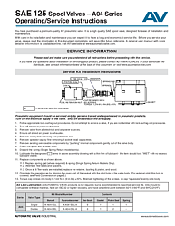
SAE 125 Spool Valves Operating and Service Instructions (A04 Series)
Overview of the SAE 125 Spool Valve Service Manual
The SAE 125 Spool Valves Operating/Service Instructions document (Form AV-SAE-125-OI) provides comprehensive guidance for installing, servicing, and maintaining Automatic Valve's A04 Series pneumatic spool valves. These premium-quality SAE 125 spool valves are engineered for reliable performance in industrial pneumatic systems, and this manual ensures operators and maintenance technicians have the information they need to maximize valve service life.
This document is an essential reference for anyone responsible for the installation, field servicing, or troubleshooting of A04 Series SAE 125 spool valves. It covers the complete service kit installation process, solenoid wiring configurations, external pilot field conversion procedures, manifold base assembly instructions, and critical safety cautions and warnings. Whether you are performing routine preventative maintenance or a full valve rebuild, these instructions walk you through every step.
Who Should Use This Document
This operating and service manual is intended for trained and experienced pneumatic equipment technicians. Automatic Valve strongly advises that only qualified personnel service these valves. Before performing any service, technicians must be familiar with lock-out/tag-out procedures in compliance with OSHA 1910.147 and EN 1037 standards. The document should be read in its entirety before beginning any service procedure and kept on file for future reference.
Service Kit Installation Instructions for SAE 125 (A04 Series)
The core of this manual is the step-by-step service kit installation procedure for the A04 Series spool valve. Service kits are available in both Buna-N and Fluoroelastomer seal materials to suit different operating environments. The instructions guide technicians through safe disassembly, component inspection, lubrication, and reassembly of the valve.
Pre-Service Safety Procedures
Before servicing an SAE 125 spool valve, technicians must follow a strict safety protocol. First, follow appropriate lock-out/tag-out procedures per OSHA 1910.147 — do not attempt service if unfamiliar with these procedures. Turn off electrical power to the valve. Remove the valve from all electrical and air power sources. Ensure all stored air power is fully exhausted. These steps are critical to prevent accidental energization or pressurization during service, which could cause personal injury or property damage.
Step-by-Step Disassembly and Reassembly
Once the valve is safely de-energized and depressurized, begin by removing the coil retention nut and then the coil. Remove the operator cap by extracting the 4 socket head cap screws. Gently push internal components out of the valve body. Clean the spool with a clean cloth and discard the spring on single spring return models only.
Lubricate all components marked with a '+' in the assembly drawing with a thin film of compatible lubricant — the item should appear wet with no excess lubricant visible. Reassemble the components in the correct order: replace the spring pad and spring (single spring return models), alternate tee-seals and spacers until all 6 tee-seals are installed, then replace the retainer, bushing, piston, and spool. Orientate the operator cap by aligning the open end of the gasket with the pilot hole in the valve body. Torque cap screws to 1.02 N-m (9 in-lbs) ±10%, alternating the tightening pattern so the cap squeezes evenly onto the body.
Service Kit Contents and Part Numbers
Automatic Valve offers dedicated service kits for both single and double operator A04 Series valves. The single operator kit (K-A04-SGL for Buna-N or K-A04-SGL-A for Fluoroelastomer) includes 6 tee-seals, 1 gasket, 1 piston seal, and 1 spring. The double operator kit (K-A04-DBL or K-A04-DBL-A) includes 6 tee-seals, 1 gasket, 2 piston seals, and no spring. Using only genuine Automatic Valve service kit components is essential to maintain warranty coverage and ensure proper valve function.
Wiring Configurations and Solenoid Pin-Outs
The SAE 125 operating instructions include detailed wiring diagrams for multiple connector configurations. The document covers 4-pin Micro, 5-pin Micro, and 5-pin Mini connectors across GM, Ford, and Chrysler standard wiring patterns. Each configuration includes a schematic showing solenoid A and solenoid B connections, color-coded wire identification (red, black, brown, green, blue, red/white, red/black, red/yellow), and pin-out tables mapping each pin to its corresponding solenoid terminal.
For single solenoid valves, technicians should use the Sol B pin-out. The document provides seven distinct wiring configurations (numbered 0 through 7) to accommodate different OEM connector standards, ensuring compatibility across a wide range of industrial applications. Proper wiring is critical for reliable valve operation and to prevent solenoid burnout or erratic shifting.
External Pilot Field Conversion
The manual includes instructions for converting an SAE 125 spool valve from internal pilot supply to external pilot supply in the field. This conversion is necessary when the valve operates at pressures outside the standard internal pilot range or when a separate pilot pressure source is required.
To perform the conversion, remove the valve from the sub-base and turn it upside down. Remove the 1/16 NPTF pipe plug from the external pilot supply port in the valve and install it in the internal pilot supply port. Connect the air supply to the external pilot supply port in the base. For the A04 series, the external pilot supply port uses a 1/8 NPTF fitting. The document also notes that for AC solenoids, the ground wire is screwed to the inside of the cap, while for DC solenoids, the ground wire is capped.
Manifold Base Assembly Instructions
The document provides assembly instructions for mounting SAE 125 spool valves to manifold bases in both Model 413 and Model 416 configurations. For Model 413 assemblies, the process involves placing O-rings in counterbores in the base, then assembling base-to-base using screws, washers, and nuts. For Model 416 assemblies, the steps include placing O-rings in counterbores of end caps, assembling cap to base, placing O-rings in counterbores of base, and assembling base to base. Both assembly methods follow a clear numbered sequence to ensure proper sealing and alignment.
Filtration, Lubrication, and Operating Precautions
Automatic Valve recommends installing a 5-micron rated filter to clean the air supply and prevent contaminants from interfering with valve performance. While air line lubrication is not required for Automatic Valve products, it is recommended to maximize service life. Compatible lubricants should be petroleum-based oils with oxidation inhibitors, an ISO 32 or lighter viscosity, and an aniline point between 82°C (180°F) and 99°C (210°F). Oils with phosphate-type additives should be avoided as they can harm polyurethane components and potentially lead to valve failure.
The cautions and warnings section emphasizes several critical safety points: all ROSS Group products must be used within their specification limits, only genuine ROSS Group components should be used for repairs, and overhauled or serviced valves must be functionally tested prior to reinstallation. Air supply lines should never be restricted, and exhaust silencers must have flow capacities at least as great as the exhaust capacities of the valves to prevent back pressure issues.
Warranty Information for SAE 125 Spool Valves
All Automatic Valve products, as part of the ROSS Group, are warranted for a one-year period from the date of purchase against defects in material and workmanship. Filters, regulators, and lubricators carry an extended seven-year warranty. The warranty is voided if products have been subject to misuse, misapplication, improper maintenance, modification, or tampering. Products for warranty service must be returned to the ROSS Group freight prepaid. This warranty is exclusive and in lieu of all other warranties, expressed or implied.
Frequently Asked Questions
What seal materials are available for SAE 125 spool valve service kits?
Automatic Valve offers SAE 125 (A04 Series) service kits in two seal materials: standard Buna-N and optional Fluoroelastomer. Buna-N seals are suitable for most general-purpose pneumatic applications, while Fluoroelastomer seals (option "A" suffix) provide enhanced chemical resistance and higher temperature tolerance for demanding environments. Select the seal material that matches your application's media and temperature requirements.
How do I convert an SAE 125 spool valve from internal pilot to external pilot?
To convert an SAE 125 A04 Series spool valve to external pilot operation, remove the valve from its sub-base and turn it upside down. Relocate the 1/16 NPTF pipe plug from the external pilot supply port to the internal pilot supply port. Then connect your external pilot air supply to the pilot supply port in the base using a 1/8 NPTF fitting. This conversion is useful when operating at pressures outside the standard internal pilot range.
What torque specifications are required when reassembling the SAE 125 spool valve?
During reassembly of the A04 Series SAE 125 spool valve, cap screws securing the operator cap to the body should be torqued to 1.02 N-m (9 in-lbs) ±10%. For housing screws (#10-24), the specified torque is 4.8 N-m (42 in-lbs) ±10%. Body-to-base screws (5/16-18) should be torqued to 13.7 N-m (121 in-lbs) ±10%. Always alternate tightening of screws so the cap squeezes evenly onto the body.
Is air line lubrication required for Automatic Valve SAE 125 spool valves?
Air line lubrication is not required for Automatic Valve products, but it is recommended to maximize service life. If using a lubricator, oils should be compatible with the seal material (Buna-N or Fluoroelastomer), have an ISO 32 or lighter viscosity, and have an aniline point between 82°C (180°F) and 99°C (210°F). Avoid oils with phosphate-type additives, which can damage polyurethane components.
What safety precautions must be followed before servicing SAE 125 spool valves?
Before servicing any SAE 125 spool valve, you must follow lock-out/tag-out procedures per OSHA 1910.147 and EN 1037. Turn off all electrical power, remove the valve from all electrical and air power sources, and ensure all stored air pressure is fully exhausted. Only trained and experienced pneumatic equipment technicians should perform service. Failure to follow these precautions can result in personal injury or property damage.