




ISO 5599-1 Spool Valves Operating and Service Instructions
Overview of the ISO 5599-1 Spool Valve Service Manual
The Automatic Valve ISO 5599-1 Spool Valves Operating and Service Instructions document is the authoritative reference for maintaining and servicing AV's premium-quality ISO-standard pneumatic spool valves. Designed for ease of installation and maintenance, these high-quality ISO spool valves comply with the ISO 5599-1 international standard for pneumatic fluid power valve interfaces, ensuring dimensional compatibility with other ISO-compliant valve systems and sub-bases.
This manual covers the I15, I20, and I45 series ISO spool valves in both single spring return and double solenoid configurations. Published by Automatic Valve Industrial as part of the ROSS Group, the document provides detailed assembly diagrams, step-by-step service kit installation instructions, lubrication and filtration recommendations, torque specifications, safety warnings, and complete service kit model number reference tables. It is intended for use by trained pneumatic equipment professionals responsible for valve maintenance in industrial applications.
ISO Spool Valve Series and Service Kit Options
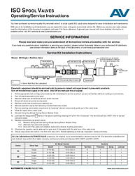
Three series of ISO 5599-1 spool valves are covered in this document. The I15 series is available with service kits K-I15-SGL (single, Buna-N), K-I15-DBL (double, Buna-N), K-I15-SGL-A (single, fluoroelastomer), and K-I15-DBL-A (double, fluoroelastomer). The I20 series, which is featured in the primary assembly diagram, uses kits K-I20-SGL, K-I20-DBL, K-I20-SGL-A, and K-I20-DBL-A. The I45 series uses kits K-I45-SGL, K-I45-DBL, K-I45-SGL-A, and K-I45-DBL-A. All single-valve kits include six tee-seals, one piston seal, one spring, and one lubricant packet. All double-valve kits include six tee-seals, two piston seals, and one lubricant packet. Both Buna-N and fluoroelastomer seal materials are available across all three series.
Step-by-Step Service Kit Installation Instructions
The service kit installation procedure for ISO 5599-1 spool valves follows a structured process that prioritizes personnel safety and ensures correct component assembly. This section details the complete procedure from initial safety preparation through final reassembly and torque verification.
Safety Preparation and Energy Isolation
Before any service work begins, pneumatic equipment should be serviced only by persons trained and experienced in pneumatic products. Turn off the electrical supply to the valve and shut off and exhaust the air supply. Follow appropriate lock-out/tag-out procedures in accordance with OSHA 1910.147 and EN 1037. Do not attempt to service the valve if you are not familiar with lock-out/tag-out procedures. Turn off electrical power to the valve. Remove the valve from all electrical and air power sources. Ensure all stored air power is completely exhausted before proceeding.
Valve Disassembly Procedure
Remove the coil by first removing the coil retention nut. Remove the operator cap by unfastening the four socket head cap screws. Remove the existing serviceable components by gently pushing the internal components out of the valve body. Take care not to damage the valve bore during this step. Clean the spool thoroughly with a clean cloth. For single spring return models only, discard the existing spring since the service kit includes a replacement. Set aside the gasket for reinstallation, as it is reusable if undamaged.
Component Lubrication and Reassembly
Apply a thin film of the supplied lubricant to all components designated with a plus sign in the assembly diagram. The items requiring lubrication include the valve body bore, the spool major diameter, the tee-seals, the bushing, and the piston seal. Each lubricated surface should appear wet with no excess lubricant visible. Reassemble the components in the following order: replace the spring pad and spring (single spring return models only), alternate tee-seals and spacers until all six tee-seals are installed, then replace the retainer, bushing, and piston. Orientate the operator cap by aligning the open end of the gasket with the pilot hole in the valve body. Torque the cap screws into the body to 1.02 N-m (9 in-lbs) with a tolerance of plus or minus 10 percent. Rotate tightening so that the cap squeezes evenly onto the body, preventing gasket distortion and ensuring a proper pneumatic seal.
Lubrication and Filtration Best Practices
Air line lubrication of Automatic Valve ISO 5599-1 spool valve products is not required but is recommended to maximize service life and reliability. When using air line lubricators, the selected oils must be compatible with the seal material installed in the valve. Compatible lubricants are petroleum-based oils with oxidation inhibitors, having an ISO 32 or lighter viscosity and an aniline point between 82 degrees Celsius (180 degrees Fahrenheit) and 99 degrees Celsius (210 degrees Fahrenheit). Avoid lubricants with phosphate-type additives, which can degrade polyurethane components and lead to premature seal failure.
Proper filtration of the compressed air supply is essential for achieving optimal valve performance and service life. Contaminants such as dirt, scale, and moisture are present in virtually every compressed air system and can interfere with valve operation if not properly filtered. The ROSS Group recommends a filter with a 5-micron rating for normal applications. Standard ROSS Group filters and lubricators with polycarbonate bowls are rated for compressed air use only. Metal bowl guards should be used where provided to minimize danger from high-pressure fragmentation in the event of bowl failure. Crazed, cracked, or deteriorated bowls should be replaced immediately.
Safety Warnings for ISO Spool Valve Service and Installation
The ISO 5599-1 spool valve operating instructions contain critical safety warnings that must be observed during all service and installation activities. These warnings are issued by the ROSS Group, which encompasses ROSS Operating Valve, ROSS Controls, ROSS DECCO, and Automatic Valve Industrial.
Pre-Installation and Service Warnings
All sources of energy must be turned off, the pneumatic system shut down and exhausted, and all power sources locked out before servicing any pneumatic component. All ROSS Group products should be installed and serviced only by trained and experienced personnel. Because products can be tampered with or may require servicing after installation, responsible personnel must inspect ROSS Group products regularly and perform all necessary maintenance. Overhauled or serviced valves must be functionally tested before being placed into service. Each product should be operated within its specification limits, and only genuine ROSS Group components should be used for repairs. Failure to follow these instructions can result in personal injury and property damage.
Exhaust and Intake Restriction Warnings
Never restrict air flow in the supply line, as doing so could reduce supply pressure below the valve's minimum operating requirements, causing erratic action. Never restrict a valve's exhaust port, as this adversely affects valve performance. Exhaust silencers must be clog-resistant and have flow capacities at least equal to the exhaust capacities of the valves. Contamination of silencers results in reduced flow and increased back pressure. These restrictions apply to all ISO spool valve installations regardless of the application type.
Hazardous Machinery Safety Requirements
Mechanical power presses and other potentially hazardous machinery with pneumatically controlled clutch and brake mechanisms must use press control double valves with monitoring devices. Double valves without self-contained monitoring devices should only be used with control systems that provide valve monitoring. Safe Exhaust (dump) valve installations should incorporate monitoring systems that inhibit further operation upon valve mechanism failure. Per applicable specifications and regulations, ROSS L-O-X and L-O-X with EEZ-ON, N06, and N16 series products are defined as energy isolation devices, not as emergency stop devices.
Warranty and Technical Support
Automatic Valve ISO 5599-1 spool valves and service kits are backed by the ROSS Group's standard one-year warranty from the date of purchase. Filters, Regulators, and Lubricators (FRLs) are warranted for seven years. During the warranty period, products are warranted to be free from defects in material and workmanship, with the ROSS Group's obligation limited to repair, replacement, or purchase price refund for products determined defective at the company's discretion.
Warranty coverage is voided by misuse, misapplication, improper maintenance, modification, or tampering. Products submitted for warranty claims must be returned freight prepaid to the ROSS Group. For technical support, product inquiries, or to locate an authorized AV distributor, contact Automatic Valve at +1-248-474-6700 or visit www.automaticvalve.com for additional resources and documentation.
Frequently Asked Questions
What does ISO 5599-1 compliance mean for these spool valves?
ISO 5599-1 is an international standard that defines the interface dimensions and mounting patterns for pneumatic fluid power directional control valves. Automatic Valve ISO spool valves that comply with this standard can be mounted on any ISO 5599-1 compliant sub-base or manifold system, providing interchangeability with other manufacturers' ISO-standard valves. This standardization simplifies system design, reduces spare parts inventory, and makes valve replacement straightforward.
What are the available service kit seal materials for ISO spool valves?
All three ISO spool valve series (I15, I20, and I45) are available with both Buna-N and fluoroelastomer seal service kits. Buna-N kits use standard model numbers (such as K-I20-SGL), while fluoroelastomer kits are identified by the -A suffix (such as K-I20-SGL-A). Buna-N is suitable for standard compressed air applications. Fluoroelastomer provides superior chemical and high-temperature resistance for more demanding environments.
What torque specification applies to the operator cap screws on ISO spool valves?
The operator cap screws on ISO 5599-1 spool valves must be torqued to 1.02 N-m (9 in-lbs) with a plus or minus 10 percent tolerance. It is essential to rotate the tightening sequence so the cap squeezes evenly onto the valve body. Uneven torquing can cause gasket distortion and air leaks, reducing valve performance and reliability.
Can I service an ISO spool valve without draining the entire pneumatic system?
No. The operating instructions explicitly state that all sources of energy must be turned off, the entire pneumatic system must be shut down and exhausted, and all power sources must be locked out before servicing any valve or pneumatic component. This requirement is mandated by OSHA 1910.147 and EN 1037 for the protection of service personnel and is a mandatory safety requirement for all ROSS Group products.
How often should ISO spool valves be inspected or serviced?
The operating instructions do not specify a fixed service interval, as the appropriate maintenance schedule depends on the application, operating environment, air quality, cycle rate, and other factors. However, the document states that persons responsible for safety must check ROSS Group products on a regular basis and perform all necessary maintenance to ensure safe operating conditions. Implementing a preventive maintenance program with periodic valve inspections is strongly recommended.