




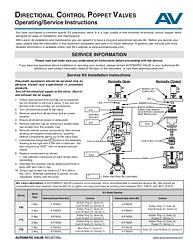
Directional Control Poppet Valves Operating and Service Instructions
Overview of the Directional Control Poppet Valve Service Manual
The Directional Control Poppet Valves Operating/Service Instructions document (Form AV-DCPV-OI) is the official maintenance and service guide for Automatic Valve's in-line mounted directional control poppet valves. Unlike spool valves that use a sliding spool to direct airflow, poppet valves use a poppet mechanism with seals and cush-n-seals that provide near-zero leakage and fast response times, making them ideal for applications requiring precise pneumatic control.
This manual covers the P06, P14, and P36 Series poppet valves in both normally open (NO) and normally closed (NC) configurations, as well as 2-way and 3-way valve types. The document provides step-by-step service kit installation instructions, details on available service kit part numbers and contents, and important cautions, warnings, and safety information. It is an essential reference for anyone tasked with maintaining or repairing Automatic Valve directional control poppet valves.
Document Purpose and Intended Audience
This document is intended exclusively for persons trained and experienced in pneumatic products. Before servicing any poppet valve, the entire manual should be read and understood. It should be saved for future reference. A general user manual with more detailed information on Automatic Valve products is available online at www.automaticvalve.com. For installation or service questions, contact Automatic Valve directly or an authorized AV distributor.
Service Kit Installation Instructions for Poppet Valves
The manual provides a comprehensive step-by-step procedure for servicing directional control poppet valves. The instructions apply to normally open and normally closed configurations across the P06, P14, and P36 Series, with assembly diagrams showing the differences between NO and NC valve internal layouts.
Pre-Service Safety and Lockout Procedures
Before beginning any service work, technicians must follow strict safety protocols. Implement appropriate lock-out/tag-out procedures per OSHA 1910.147 and EN 1037 — do not attempt service if you are not familiar with these procedures. Turn off the electrical supply to the valve. Shut off and exhaust the air supply. Remove the valve from all electrical and air power sources. Ensure all stored air power is fully exhausted. These steps are mandatory to prevent injury from unexpected pressurization or electrical energization.
Disassembly Procedure
To begin disassembly, remove the operator cap by extracting the 4 socket head cap screws. Next, remove the internal screws concurrently — this step is critical for poppet valves. After removing internal screws, push the existing serviceable components gently out of the valve body. The manual emphasizes concurrent removal of internal screws to prevent component damage and ensure controlled disassembly. For the P36 Series specifically, a wear ring is included in the assembly and must be noted during disassembly.
Lubrication and Reassembly
Lubricate all components designated with a '+' marker in the assembly drawing with a thin film of compatible lubricant. Components should appear wet with no excess lubricant visible. Replace all components as shown in the assembly diagrams, noting the differences between normally open and normally closed valve configurations.
When reinstalling internal screws, use retention compound on each screw. Orientate the operator cap by aligning the pilot hole in the body with the pilot hole in the cap. Torque cap screws into the body to 6.7 N-m (59 in-lbs) ±10%, alternating the tightening of screws so the cap squeezes evenly onto the body. This even compression is important for proper sealing and long service life.
Normally Open vs. Normally Closed Valve Configurations
The assembly drawings in the manual clearly distinguish between normally open (NO) and normally closed (NC) poppet valve configurations. NC valves have a specific arrangement of seals, a rubber plug, a cush-n-seal, and seals with a spring. NO valves have a slightly different internal component layout with seals and cush-n-seals arranged to maintain the valve in the open position by default. Understanding the correct component orientation for your specific valve type is critical for successful reassembly. The rubber plug must be removed by extracting internal screws concurrently, and retention compound must be used when reinstalling these screws.
Service Kit Part Numbers and Contents by Series
Automatic Valve provides dedicated service kits for each poppet valve series and configuration. The kits are organized by series (P06, P14, P36), valve type (2-way or 3-way), and normally closed or normally open configuration.
For the P06 Series: The 2-way NC kit (K-P0600J) includes 1 rubber plug, 5 seals, 1 cush-n-seal, and 1 spring. The 2-way NO kit (K-P0600K) includes 1 rubber plug, 4 seals, 2 cush-n-seals, and 1 spring. The 3-way NC kit (K-P0600G) includes 1 rubber plug, 4 seals, 2 cush-n-seals, and 1 spring. The 3-way NO kit (K-P0600H) includes 1 rubber plug, 4 seals, 2 cush-n-seals, and 1 spring.
For the P14 Series: The 2-way NC kit (K-P1400J) includes 1 rubber plug, 6 seals, 1 cush-n-seal, and 1 spring. The 2-way NO kit (K-P1400K) includes 1 rubber plug, 5 seals, 1 poppet, and 1 spring. The 3-way NC kit (K-P1400G) includes 1 rubber plug, 4 seals, 2 cush-n-seals, and 1 spring. The 3-way NO kit (K-P1400H) includes 1 rubber plug, 4 seals, 1 poppet, and 1 spring.
For the P36 Series: The 2-way NC kit (K-P3600J) includes 1 wear ring, 5 seals, 2 cush-n-seals, and 1 spring. The 2-way NO and 3-way kits (K-P3600K, K-P3600G, K-P3600H) include 5 seals, 2 cush-n-seals, and 1 spring. The P36 Series is the only poppet valve series that includes a wear ring in its service kits.
Filtration and Lubrication Requirements
Air line lubrication of Automatic Valve poppet valves is not required but is recommended to maximize service life. Compatible lubricants should be petroleum-based oils with oxidation inhibitors, an ISO 32 or lighter viscosity, and an aniline point between 82°C (180°F) and 99°C (210°F). The ROSS Group recommends a 5-micron rated filter for normal applications to prevent dirt, scale, moisture, and other contaminants from entering the valve and causing premature wear or seal damage.
Polycarbonate filter and lubricator bowls are designed for compressed air applications only. Do not expose these products to alcohol, liquefied petroleum gas, or other fluids that can cause bowls to rupture. Always use the metal bowl guard where provided. Immediately replace crazed, cracked, or deteriorated bowls to prevent hazardous high-pressure fragmentation.
Safety Cautions and Warnings
The document includes comprehensive safety cautions and warnings from the ROSS Group. Before servicing any pneumatic component, all sources of energy must be turned off, the entire pneumatic system shut down and exhausted, and all power sources locked out per OSHA 1910.147 and EN 1037. Only trained and experienced pneumatic technicians should perform service. All ROSS Group products must be used within their specification limits, and only genuine ROSS Group components should be used for repairs.
Do not restrict air flow in the supply line, as this could reduce pilot supply pressure below minimum requirements and cause erratic valve action. Do not restrict a valve's exhaust port as this can adversely affect poppet valve operation — poppet valve exhaust ports must never be restricted, unlike spool valve exhaust ports which can be restricted for speed control. Exhaust silencers must be resistant to clogging and must have flow capacities at least as great as the exhaust capacities of the valves.
Warranty for Directional Control Poppet Valves
All Automatic Valve directional control poppet valves carry the ROSS Group standard one-year warranty from the date of purchase against defects in material and workmanship. Filters, regulators, and lubricators carry a seven-year warranty. Warranty coverage is voided by misuse, misapplication, improper maintenance, modification, or tampering. Products submitted for warranty evaluation must be returned to the ROSS Group freight prepaid. This warranty is exclusive and in lieu of all other warranties expressed or implied.
Frequently Asked Questions
What is the difference between a poppet valve and a spool valve?
Poppet valves use a poppet mechanism with seals and cush-n-seals to direct airflow, while spool valves use a sliding spool with tee-seals. Poppet valves typically offer near-zero leakage and faster response times, making them ideal for applications requiring precise control. However, poppet valve exhaust ports must never be restricted, unlike spool valves which allow exhaust restriction for speed control. Automatic Valve offers both types to meet diverse pneumatic system requirements.
Why must retention compound be used on internal screws during poppet valve reassembly?
Retention compound (thread-locking adhesive) is required on internal screws during poppet valve reassembly to prevent the screws from loosening during operation. Poppet valves experience rapid cycling forces that can gradually work screws loose without retention compound. Additionally, the internal screws must be removed concurrently during disassembly to prevent component damage, and reinstalled with retention compound to ensure secure, vibration-resistant fastening.
What makes the P36 Series poppet valve different from the P06 and P14 Series?
The P36 Series is the largest poppet valve in the Automatic Valve directional control lineup and includes a wear ring that is not present in the P06 or P14 Series. The P36 wear ring is included in the service kit and must be replaced during service. The P36 service kits also have slightly different component counts compared to the smaller series. The P14 Series NO kits uniquely include a replacement poppet component.
Can poppet valve exhaust ports be restricted for cylinder speed control?
No — this is a critical difference between poppet valves and spool valves. Poppet valve exhaust ports must not be restricted, as restriction can cause valve malfunction. For cylinder speed control with poppet valves, use separate flow control valves in the system instead. Spool valve exhaust ports, by contrast, may be restricted to provide speed control for cylinders or other devices.
What are the torque specifications for directional control poppet valve cap screws?
Cap screws for all Automatic Valve directional control poppet valves (P06, P14, and P36 Series) should be torqued to 6.7 N-m (59 in-lbs) ±10%. Always alternate the tightening of screws so the cap squeezes evenly onto the body, ensuring proper seal compression and preventing leaks. Using a calibrated torque wrench is recommended for accurate and consistent fastening.